When selecting a power system, distribution network or industrial application, the core construction type is one of the more basic decisions that must be made when specifying a transformer. However the core type choice of shell-type or core-type transformer cores is often glossed over in product datasheets, without which engineers and buyers often miss key information.
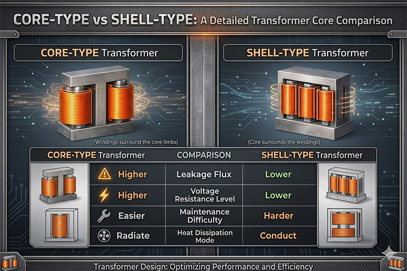
The structural difference between these two designs is simpler than it seems: a core-type transformer wraps the core with the windings; and a shell-type transformer wraps the windings around the core. Yet, this one design difference gives rise to important differences between the two: efficiency, cooling, mechanical strength, insulation complexity, access for maintenance and all in the total cost of ownership.
This handy reference helps you to understand the engineering tradeoffs associated with each type of core and guide you toward the right decision for your application.
What Is a Core-Type Transformer?
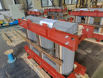
A core type transformer has a rectangular laminated core of silicon steel strips cut in an L-shape. The core consists of two vertical limbs and two horizontal yoke laminations. The primary and secondary windings are split into halves and wound concentrically on the limbs (often with the low-voltage winding poured up against the core and the high-voltage winding when outside).
This prevents the insulation cost between the core and the high-voltage winding, as the low-voltage coil acts as a buffer. The windings are cylindrical in shape; it is only after the winding is finished that the laminations are slipped in.
Key structural characteristics:
- Two magnetic limbs (two-limb design)
- L-shaped laminations stacked in alternating direction to break the line of continuous joints
- Concentric (cylindrical) winding scheme
- Two distinct magnetic circuits;
- Rectangular cross-section
A core-type transformer provides a uniform flux distribution, since flux is split equally between the two side limbs. This configuration also exposes the windings more, improving natural air and oil cooling which is important for high power transformers.
Core type transformers are the more prevalent type used on power system. They tend to be the default choice for power generation, transmission and distribution due to the simpler design, lower cost of manufacturing and ease of maintenance.
What is a Shell Type Transformer?
A shell type transformer employs a reversed method: the windings are encased by the core. The transformer is formed of three “branches”: the middle one, which transports the flux; the other two, which block half of the flux each.
The core and secondary windings are both centered on the central limb. Both windings are divided into sections, and the low-voltage and high-voltage subsections are placed alternately. This is known as the sandwich or disc winding and is what gains shell-type transformers their nickname- the sandwich transformer.
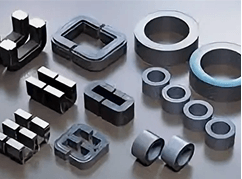
The shells of a shell-type transformer are formed by cutting the laminations into E-shaped and I-shaped (or combined E and L) strips and constructing the shells around the pre-wound coil.
Key structural characteristics:
- 3 magnetic limbs (central limb + 2 outer limbs)
- Laminations of the E-shape and I-shape (or L-shape)
- Arranagment of the winding (sandwich (disc))
- Single magnetic circuit
- Square or cruciform cross-section
The central limb has the entire magnetic flux passing through it so it needs to be double the width of each outer limb. The overall geometry leads to a shorter average magnetic path length which means less magnetizing current and potentially higher efficiency of energy transfer per unit power.
Core-Type vs Shell-Type: A Detailed Comparison
1. Construction and Lamination
The lamination profile is the most apparent physical difference in the two designs.
- Core-type:in the L-shaped laminations are npaced by stacked whole lamination; in order to Avoid a continuous joint that would form a high reluctance air-gap, and therefore increase core losses.
- Shell-type:E and I-shaped laminations are put around the coil. This geometry is more complicated but provides the best mechanical containment of the winding. However, this type is more demanding in winding assembly.
Another difference is in the cross sectional shape: core-type cores are normally rectangular, so are the box-type cores, but the others are square, cruciform, two and three stepped, respectively, according to power rating.
The increased fill factor provided by the stepped cruciform cross-section in the larger shell types results in higher fill factor in round winding bores leading to less iron and copper losses, a major benefit at high kVA levels.
2. Winding Configuration
The winding topology is very different between the two designs and largely drives all of the downstream performance differences.
- Core-type:Concentric cylindrical windings. Low voltage winding is located nearest to the core limb, with the high voltage winding surrounding it. The primary and secondary windings are split between the two limbs to reduce leakage flux. Easy to manufacture, test and repair.
- Shell- type: Sandwich (disc) windings. Primary and secondary windings consist of several flat pancake coils which are interleaved alternately on the center leg of the core. The inter-leaving yields a high magnetic coupling between windings and suppresses leakage reactance.
Practical implication: interleaving in shell type windings leads to lower leakage inductance values, which is a critical issue at surge protection. In the same EPRI study on distribution transformers, inductance values for the interlaced shell type at 10 kvA are of the order of 18 H while for non interlaced shell type windings they are larger than 200n H 10 times higher, with a direct consequence on lightning surge behavior.
3. Magnetic Circuit and Flux Distribution
- Core-type:Two separate magnetic circuits. The flux from the secondary is evenly divided between the two limbs of the core. The equal division of flux reduces the core losses per limb. It makes the design predictable over a broad range of operating conditions.
- Shell-type: Single magnetic circuit. The flux passes through the central limb and the other 2 limbs each carries a flux of a half of the total flux. Because of the shorter length of magnetic circuit of the shell-type, the magnetizing current needed to set up the working flux is less and hence, the no-load loss is reduced.
This is a significant efficiency advantage at partial loads an important consideration since distribution transformers usually operate around 30 50percent of their rated load for most of their service life.
4. Cooling and Heat Dissipation
None of the following differences are as critical to the functionality of each design, one in particular stands out… cooling is a major variance that separates a traditional design from a modern one.
- Core-type:Best natural cooling. As the windings are on the outside of the core they transfer heat better to the oil or air around them. These are used on large oil immersed (ONAN) and forced air cooled (ONAF/OFAF) systems on large power transformers.
- Shell-type: Poor natural cooling at the bottom. The core surrounds the windings so the heats no longer radiates directly from the surface of the coil to the cooling medium being used. Heat generated in the interior windings has to conduct out through several layers before reaching the oil or air. The main reason for low popularity of shell-type transformers in high-power, large size transformers is indicated here.
Though, the even distribution of the electromagnetic forces across the sandwich winding, which utilizes the multiple electromagnetic steering shapes, spreads the thermal stress more evenly over the winding assembly and reduces hot spots an advantage in relatively moderate power applications.
5. Mechanical Strength
- Core-type: innately less mechanically robust. Bracing against the high electromagnetic forces produced by short-circuit or inrush currents is hindered by the two-limb open construction. Extra clamping arrangements are necessary on the larger machines.
- Shell-type: Cell structure aids greatly to the found mechanical strength. The shell structure simply acts as a rigid framework which surrounds the windings, and the sandwich winding arrangement provides high inter-layer support. The structure of the core itself essentially acts as a brace. Clearly, then, shell types are more robust during fault conditions – a huge bonus for industrial applications or in transient-prone locations.
6. Insulation Requirements
- Core-type:Less insulation cost. Because the low-voltage winding is put close to the core, it decreases the voltage gradient that insulation to take. Due to the low-voltage winding is just in the top of high-voltage winding, it needs less insulation to get the clearance to the core.
- Shell-type: higher insulation cost. The three-limb construction and interleaved winding arrangement necessitate extra layer of insulation between each winding portion. This increases the cost of material and complexity in assembly, especially for high voltage designs.
7. Copper and Iron Content
- Core-type:Requires more copper conductors. Because the distributions on two separate limbs of the windings the mean turns length becomes longer and conductor material is used up.
- Shell type: Needs a greater amount of iron (core steel). Due to the increased complexity of the core geometry, more lamination material is required. The shorter mean winding length decreases the conductor volume which slightly reduces the amount of iron required.
Since the cost of transformer construction is driven mainly by the cost of the transformer material, where the price of copper is a significant factor in cost as they often are, the shell-type can be more economical; and where the price of silicon steel is high, the core-type may be more cost effective.
8. Maintenance and Repairability
- Core type: Easier to maintain. Open framework makes it easier to get access to the windings for inspection, testing or rewinding (fewer components to remove). Open framework makes visual inspection and location of faults easier during field service.
- Shell-type– More complex maintenance. Disassembly of the core from around the winding is more involved. When on site repair is needed, this is reflected by longer down time and increased service costs.
A life cycle cost issue for utilities and industral operators with large numbers of transformers may be lifetime cost of long term maintenance differentiation between shell and core type designs.
Head-to-Head Comparison Table
| Parameter | Core-Type | Shell-Type |
| Core surrounds winding | No | Yes |
| Number of limbs | 2 | 3 |
| Lamination shape | L-shaped | E & I / E & L shaped |
| Winding type | Concentric (cylindrical) | Sandwich (disc/pancake) |
| Magnetic circuits | 2 | 1 |
| Magnetic path length | Longer | Shorter |
| Flux distribution | Balanced (equal in both limbs) | Central limb: full flux; outer limbs: half |
| Magnetizing current | Higher | Lower |
| Copper requirement | Higher | Lower |
| Iron requirement | Lower | Higher |
| Cooling | Better (natural) | Poorer (natural) |
| Mechanical strength | Lower | Higher |
| Insulation requirement | Lower | Higher |
| Maintenance ease | Easier | More complex |
| Cross-section shape | Rectangular | Square / cruciform |
| Typical applications | High-voltage, power/distribution | Low-voltage, electronic, industrial |
| Global market share | Dominant (worldwide) | Common in North America; niche globally |
Applications: When to Use Each Design
When Core-Type Transformers Are the Right Choice
Core-type transformers are the backbone of the world-wide power system. The inherent simplicity in their design, their ability to cool well, cheaper insulation and their ease of maintenance makes them the transformer of choice in:
- High voltage power transmission transformers (138 k V and above)
- Distribution transformers (pole-mounted and pad-mounted, 15 k V–35k V class)
- Autotransformers in Transmission Substations
- The step-up transformer at the power station
- Oil immersed-cooling large electric power industrial-type transformer
- Any application where field maintenance is the most important consideration
Most of the transformers which have been manufactured and are being used all over the world are core types. Such a large number of application for transformers mean that more engineers are aware of this type of design, and spare parts are easily available, and service facilities are more developed.
When Shell-Type Transformers Are the Right Choice
If the priority is on maintaining a compact design, mechanicalstrength, and operating efficiency at lower voltages rather than ease of cooling or access for maintenance, the preferred transformer form is the shell-type. (Suitable applications are;)
- Distribution transformers working at low-voltage (secondary network transformers)
- Electronics and instrumentation transformers in control panels
- Power supply transformers for Industrial machinery
- High frequency transformers where short magnetic path length greatly reduces core losses
- Furnace and rectifier transformers where fault current resistance is important8. This is of course where the current, during a fault condition, passes via the primary of the transformer i.e. parallel type transformer rectifier arrangements.
- North American utility applications where shell-type designs have precedent and infrastructure support
The shell-type windings are likewise recommended where there is a requirement for surge withstand capability. The lapped sandwich winding naturally provides a windings of lower inductance and improved surge distribution.
Performance Considerations at Different kVA Ratings
The severity of the performance tradeoffs between the core-type and shell-type designs is not constant across all power ratings. Knowing how each design minimizes the performance tradeoffs with respect to the kVA size can limit the design choices.
At smaller kVA sizes (less than 50 kVA): The variation in winding inductance between interlaced and non-interlaced windings is most significant. Distribution shell-type designs with interlaced windings offer a distinct benefit in lightning surge performance at this size range. In this size range, non-interlaced shell-type designs have been statistically shown by research done from IEEE Power Apparatus and Systems to be more prone to secondary surge failures.
At moderate kVA sizes (50 kVA – 500 kVA): KVA shell and core differences is significantly less. For this range the choice turns between the cooling requirements, mechanical environment and total cost of ownership. While shell type is the easier fault current withstand, the core type are cheaper to buy and maintain;
Power transformers of large kVA range (above 1 MVA): Core type construction is prevalent. The open winding configuration offers enhanced cooling, the cylindrical form of winding has been proven in controlling short-circuit forces, and the smaller assembly steps involved make it a natural choice for large power transformers. Shell type construction can be made at this scale, although it is rarely opted for, except where dictated by regional or end-user criteria.
A Note on Regional Preferences
A second aspect that nearly catches many engineers is the large regional preference for how transformer winding are built.
In Europe, Asia, and most of the third world, core-type transformers are the most common. By and large, all IEC standards have been written around core-type construction, and most of the worldwide transformer manufacturers still default to this.
The penetration of shell-type transformers is significantly greater in the north American market and is observed across all distribution applications. This is attributed to a long history of manufacturing experience within North America, the utility specifications developed in the mid-‘50s and the performance benefit offered by the shell type distribution transformers with the operating conditions characteristic of North American distribution systems (higher number of lighting induced surges).
Knowing this regional bias can avoid specification conflicts and delays due to procurement issues when specifying transformers for international projects or cross border supply chains.
Frequently Asked Questions
Q: What is the main difference between a core-type and shell-type transformer?
A: The primary difference is that in a core-type transformer, the windings are sit on the outside of the core limbs, whereas in a shell-type transformer the windings are enveloped by the core. That is the only difference in structure, and can be seen to account for all differences in downstream performance, cooling, insulating and maintenance requirements.
Q; Which is more efficient, core or shell type?
A: Practical efficiencies of power transformers of the two types are very similar, typically within a few tenths of a percent, at all loads. The efficiency of the shell type compared to the core type depends upon the operating point. For example, shell type transformers advantageously have a relatively short magnetizing path, thus reducing no load core loss as well as magnetizing current; this advantage is exploited at partial load. The core type (more specifically an older design with larger leakage flux) suffered less leakage flux which is advantageous at full load.
Q: Why are the core-type generally used in high-voltage?
A: Core-type have superior natural cooling as the winding is completely surrounded by the cooling medium as opposed to being sealed by the core. Managing heat dissipation becomes more critical at high voltages and power levels. Cylindrical concentric windings can more easily cope with short-circuit EMF‘s in large units.
Q: What affords good mechanical strength in the shell type transformer?
A: In a shell type transformer, the core structure that encloses the windings provides the necessary mechanical strength by supporting a hold-in-place action. In addition the nature of the sandwich winding does not leave the layers open to withstand the full effects of any fault currents. A core type has the external bracing structures to resist this.
Q: Which type of transformer is more time-consuming to maintain?
A: It is key to note that the core-type transformers are substantially more straightforward to care for since they are built open with direct access to the windings for business purposes. It is necessary to partially dismantle the centerpost in shell-type transformers, therefore time-consuming servicing.
Q: Is a shell type transformer more expensive?
A: In most cases, yes. Because shell type transformers require a more complicated lamination geometry, more complicated winding configurations, and an increased amount of iron core material, the added manufacturing difficulty usually makes the initial purchase price higher than a comparable core type transformer. Lower conductor (copper/aluminum) requirements cancel out some of the added cost, and increased mechanical strength also often benefits lifecycle costs in harsh operating conditions.
Conclusion
Core-type vs. Shell-type transformer cores is not a matter of preference. It is an engineering decision that has quantitative impact on efficiency, reliability, cooling, service life and ultimately “lifetime costs”.
It is for a reason that core types are still the world norm. Their more straightforward construction, better natural cooling, cheaper insulation and easier maintenance make them the best choice for most high voltage power and distribution applications. If you are specifying a transformer for a utility scale or industrial power application then core type should be the first type you consider.
Shell-type transformers are acceptable for applications demanding mechanical strength, shorter magnetic path, or space economies over ease of cooling. These transformers are especially suitable for low-voltage industrial and electronic uses, and are still available in some North American distribution configurations.