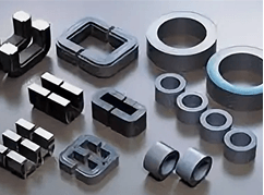
EI transformer core is the core magnetic circuit component of the transformer. It is named so because it is composed of “E” -shaped and “I” -shaped silicon steel laminates stacked alternately. It is an indispensable basic component in power transmission and distribution equipment. Its core function is to conduct magnetic flux and achieve efficient conversion of electrical energy.
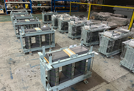
It is widely used in the field of power frequency transformers. With the advantages of simple structure and stable performance, it has become the mainstream choice in the medium and low voltage distribution market . Compared with toroidal and R-type cores, EI cores are more suitable for large-scale mass production, with controllable costs and convenient maintenance, making them the preferred core components for transformer manufacturers.

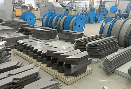
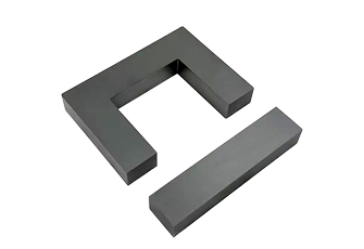
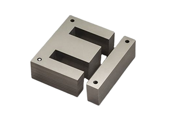
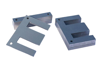
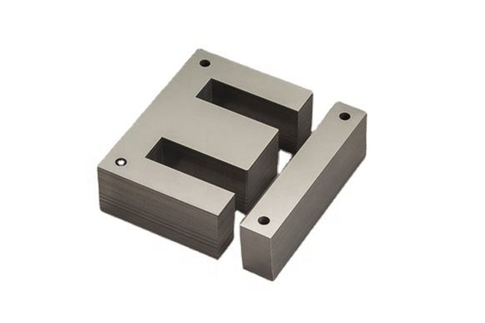
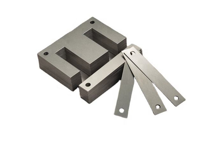
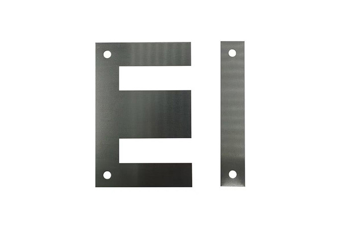
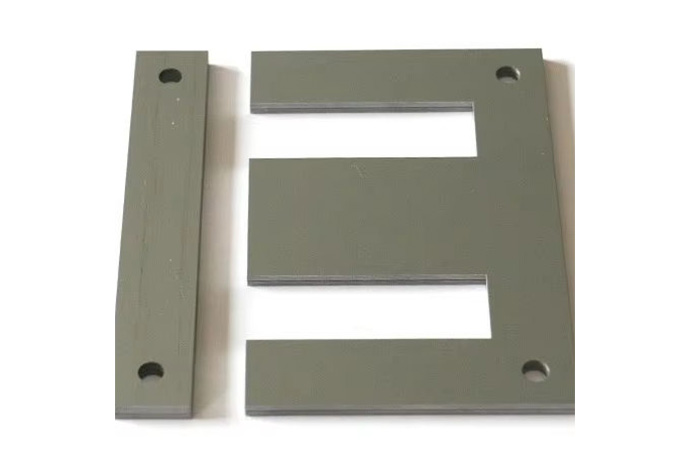
The core structure of the EI transformer core is composed of E-shaped and I-shaped laminations. All laminations are covered with insulating coatings on their surfaces and form a closed magnetic circuit through interlaced stacking .
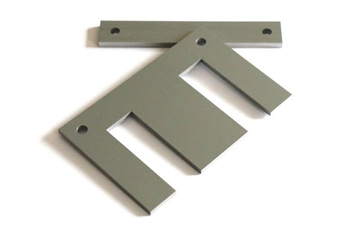
The E-shaped laminated plates present a structure of three horizontal and one vertical, responsible for the conduction of the main magnetic flux. The I-shaped laminated plate is long and strip-shaped, used to close the magnetic circuit and reduce magnetic flux leakage.
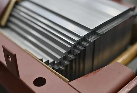
The thickness of the laminations is usually 0.35 to 0.5mm. They are formed by precise stamping to ensure a tight fit between the laminations, effectively reducing hysteresis loss and eddy current loss, and improving the overall energy efficiency of the core.
This structural design makes the core assembly convenient, allowing the number of laminations to be adjusted as needed, and the thickness and capacity of the core to be flexibly changed.
| Model | Center Leg Width (mm) | Stack Height Range (mm) | Typical Power Rating (VA) | Core Loss (W/kg @ 1.7T / 50Hz) | Saturation Flux Density (T) | Approx. Weight (kg @ 30mm stack) | Efficiency (%) | Operating Temp. (°C) |
| EI-28 | 28 | 10–25 | 5–20 | ≤ 1.15 | 1.9 | 0.08–0.15 | ≥ 92 | -40 to +70 |
| EI-35 | 35 | 15–30 | 15–50 | ≤ 1.10 | 1.95 | 0.18–0.28 | ≥ 94 | -40 to +85 |
| EI-41 | 41 | 20–35 | 30–100 | ≤ 1.05 | 1.95 | 0.32–0.45 | ≥ 95 | -40 to +90 |
| EI-48 | 48 | 20–40 | 50–200 | ≤ 1.00 | 1.95 | 0.45–0.65 | ≥ 96 | -40 to +100 |
| EI-57 | 57 | 25–50 | 100–400 | ≤ 0.95 | 1.95 | 0.75–1.05 | ≥ 96.5 | -40 to +105 |
| EI-66 | 66 | 25–60 | 200–800 | ≤ 0.90 | 1.95 | 1.10–1.65 | ≥ 97 | -40 to +110 |
| EI-76 | 76 | 30–70 | 500–1,500 | ≤ 0.85 | 1.95 | 1.80–2.50 | ≥ 97.5 | -40 to +120 |
| EI-86 | 86 | 35–80 | 800–3,000 | ≤ 0.80 | 1.95 | 2.60–3.80 | ≥ 98 | -40 to +130 |
| EI-105 | 105 | 40–100 | 2,000–5,000 | ≤ 0.75 | 1.95 | 4.50–6.50 | ≥ 98 | -40 to +140 |
| EI-133 | 133 | 50–120 | 5,000–15,000 | ≤ 0.70 | 1.95 | 9.00–14.00 | ≥ 98.5 | -40 to +150 |

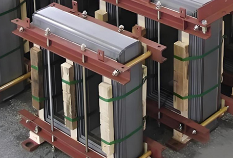
The magnetic flux path of the EI transformer core follows a closed loop design. When an alternating current is passed through the coil, an alternating magnetic field is generated. The magnetic flux enters from the middle column of the E-shaped laminates, is conducted through the two side columns to the I-shaped laminates, and then returns to the middle column from the I-shaped laminates, forming a complete closed magnetic circuit. This path design can minimize magnetic flux leakage to the greatest extent, enhance magnetic permeability and ensure the efficiency of electrical energy conversion. Meanwhile, the insulating coating of the laminated plates can block the path of eddy currents, prevent excessive heat generation due to eddy currents, stop the core from overheating and being damaged, and extend the service life of the transformer.
The reason why EI cores have become the mainstream choice in the transformer field is mainly due to four advantages:
4.Easy maintenance with a simple disassembly structure. Low-cost subsequent maintenance and replacement, widely compatible with power distribution equipment across multiple sectors including power, industrial, and building applications.
| Series Name | Type | Main Applications | Characteristics |
| EI28 Series | Small EI Core | Small power adapters, micro-transformers | Compact size, low power consumption, suitable for low-power electronic devices |
| EI35 Series | General-purpose small core | Household small transformers, LED drive power supplies | Suitable for a moderate power range, excellent cost-effectiveness, strong mass production stability |
| EI41 Series | Medium-small core | Transformers for industrial control equipment and small power distribution equipment | Combines advantages in size and performance |
| EI57 Series | Medium core | Industrial control transformers, voltage stabilizers | Wide power coverage, strong anti-interference ability, stable magnetic properties |
| EI66 Series | Medium-large core | Power transformers, distribution transformers | High power carrying capacity, outstanding low iron loss performance |
| Custom Size Series | Non-standard EI core | Various devices suitable for special power and installation scenarios | Customized according to customer’s technical drawings and size parameters, supports full-process services from design to mass production |
| Material Type | Sub – Grade | Characteristics | Suitable Scenarios | Advantages |
| CRGO Oriented Silicon Steel | M3 | High magnetic permeability and extremely low iron loss; has the lowest iron loss among CRGO oriented silicon steels | High – energy – efficiency scenarios for medium – and high – end power transformers | Meets high – energy – efficiency requirements and reduces energy loss |
| CRGO Oriented Silicon Steel | M4 | High magnetic permeability and extremely low iron loss; offers good cost – effectiveness | Conventional industrial transformers | Reduces the no – load loss of transformers, meets energy – saving requirements, and has relatively reasonable costs |
| CRGO Oriented Silicon Steel | M5 | High magnetic permeability and extremely low iron loss; offers good cost – effectiveness | Civil transformers | Reduces the no – load loss of transformers, meets energy – saving requirements, and has relatively reasonable costs |
| Non – Oriented Silicon Steel | – | Good machinability, moderate cost, and stable magnetic properties | Medium – and low – power transformers, small power distribution equipment, household appliances, and small industrial equipment | Meets the usage requirements in conventional scenarios and balances performance and cost |
| Low – Loss Silicon Steel Material | – | Higher standards, with no – load loss reduced by more than 60% | Transformer scenarios with energy – saving requirements | Significantly reduces no – load loss and improves energy – saving effects |
Step 1: Provide drawings or parameters
The customer uploads CAD drawings or specifies dimensions, materials, quantities, and purposes.
Step 2: Engineering assessment
Engineers quickly review and confirm feasibility, providing an accurate quote.
Step 3: Sample confirmation
A production sample is provided for the customer to test and install for verification.
Step 4: Mass production
After sample confirmation, start standardized mass production.
Step 5: Global delivery
After completing quality inspection, packaging, and arranging logistics, global export and distribution are arranged.