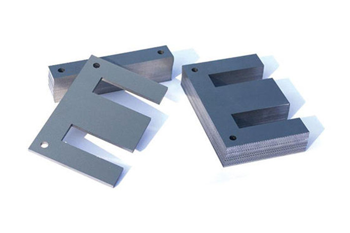

A laminated transformer core is an electrical and magnetic assembly consisting of thinly insulated layers of silicon steel—laminated to produce a low-loss path for an alternating current (AC) magnetic circuit. Each lamination is electrically insulated from every other lamination by means of surface coating or oxide layer which may range in thickness between 0.1 and 0.5 mm. This assembly will contain and control the circulation of eddy currents, which are the principal no-load core loss source in AC.
The power frequency application (50 Hz—400 Hz) relies on the laminated core, which is the state of the art for distribution transformers, industrial control transformers, audio output transformers, and power conditioning. In addition to the advantages over the solid iron core, using a laminated core enables high magnetic permeability with minimal losses and heat buildup.
An alternating magnetic flux through a metallic core generates circulating electrical currents_ that also flow within the core and known as eddy currents. These circulate to generate resistance heating and efficiency loss in the transformer.
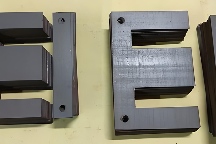
Lamination divides the core into a number of very thin electrically-isolated slices. Each slice reduces the cross-section through which eddy current can circulate. The finer the lamination, the smaller the circulating eddy current loop — and consequently the lower the core loss.
Its standard assembly process is as follows:
State the statement if the steps above are taken after the assembly of the iron core, it can not only efficiently conduct alternating magnetic flux for transformer energy conversion, provide a stable electromagnetic path, but also can effectively block the formation of useless eddy current, minimize eddy current loss, to protect the transformer long-term stable operation.
| Parameter | Value / Range |
| Lamination Thickness | 0.10 mm, 0.20 mm, 0.27 mm, 0.30 mm, 0.35 mm, 0.50 mm |
| Silicon Content | 0.5% – 4.5% Si (grain-oriented or non-oriented) |
| Core Loss (W/kg) at 1.5 T / 50 Hz | 0.80 – 2.80 W/kg (verify with manufacturer) |
| Saturation Flux Density | 1.8 T – 2.03 T (verify with manufacturer) |
| Stacking Factor | 0.93 – 0.98 |
| Operating Frequency | 50 Hz – 400 Hz |
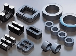
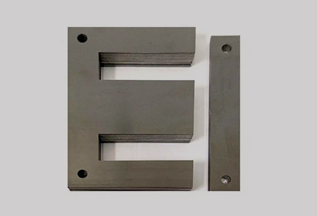
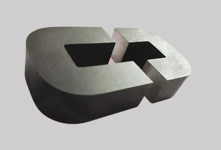
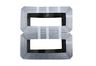
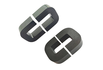
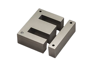
| Available Geometries | EI, UI, EE, LL, toroidal, cut C-core |
| Insulation Coating | Inorganic (C5), semi-organic (C4), organic (C6) |
| Annealing Treatment | Stress-relief annealing available post-cutting |
| Maximum Operating Temperature | 130°C – 180°C (class B to class H insulation) |
Parameters marked “verify with manufacturer” are representative industry values and should be confirmed before design finalization.

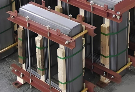
Laminated transformer cores are the magnetic core for many electrical apparatus working at power frequency. The low core loss, high saturation flux density and dimensional stability of this type of cores makes them ideal for high volume and specialty custom applications.
Typical applications include:
Choosing a laminated transformer core depends on four parameters that must be met for your application: geometry, material grade, lamination thickness, and surface treatment.
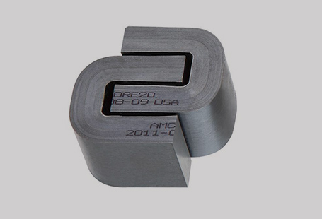
Geometry choice: EI cores are the best in terms of cost for common single-phase transformers. UI and EE cores are suitable for split-bobbin or push-pull winding arrangements. C-cores and toroidal laminates are used where low stray flux and minimal volume are desired.
Material grade: Non-oriented silicon steel (such as 50W470, 35W300) are more suitable for applications that require changing flux directions. Grain-oriented grades (such as 30Q130, 27Q120) provide better efficiencies in single phase applications where flux is more uniaxial in nature.
Lamination thickness: 0.50 mm for 50 Hz distribution transformers where cost is the primary factor. 0.27 – 0.35 mm for low-loss efficiency transformers (classified IE3 or higher). 0.10 – 0.20 mm for higher frequency (200-400 Hz) applications.
Insulation and annealing: The effects of annealing the cut c-core samples after cutting should be considered as mentioned above to alleviate the magnetic properties deterioration caused by the cutting operation. For humid or corrosive atmosphere, indicate C5 or C6 inorganic coating.
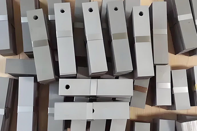
Minimum quantity orders and lead times also depend on geometry and material grade–please speak to our sales team for production volume pricing.
| Criteria | Laminated Silicon Steel Core | Amorphous Metal Core | Ferrite Core |
| Operating Frequency | 50 Hz – 400 Hz | 50 Hz – 1 kHz | 10 kHz – 3 MHz |
| Core Loss (relative) | Medium | Very Low | Low–Medium |
| Saturation Flux Density | 1.8–2.0 T | 1.56 T | 0.3–0.5 T |
| Cost | Low–Medium | High | Low–Medium |
| Mechanical Durability | Excellent | Brittle | Moderate |
| Availability / Lead Time | Wide availability | Limited suppliers | Wide availability |
| Best For | Power frequency transformers | Ultra-low-loss distribution transformers | High-frequency switching supplies |
Summary: Laminated silicon steel cores are still the material of choice for conventional power frequency(50/60 Hz) transformer use, where high saturation density, harsh mechanical handling requirements and reasonable manufacturing costs are necessary. Amorphous gives reduced loss, but at 3-5x material costs. Ferrite has no use below 10 kHz.
Laminated cores should be made from cold-rolled silicon steel coil by IEC 60404-8-7 or equivalent national standards (GB/T 2521 China, JIS C 2552 Japan). The material from mill certic ates to finished core identification should be traceable and show silicon content, coercive force and core loss values in accordance with the grade specified.
Key manufacturing quality indicators to specify:
Require mill certificates and core loss testing reports with each batch/production run.