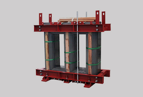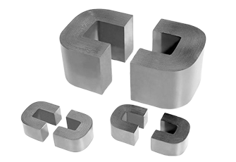
A single phase transformer core is a magnetically permeable path providing the flux path in a single phase transformer to allow transfer of power between the primary and secondary windings for a given voltage ratio.
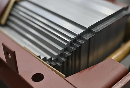
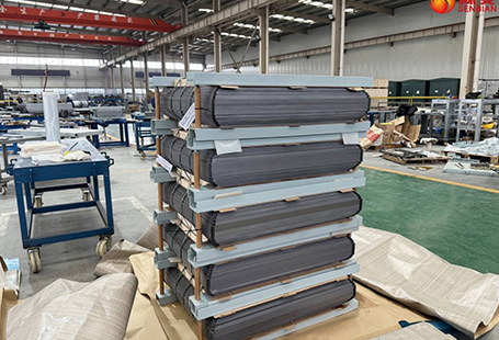
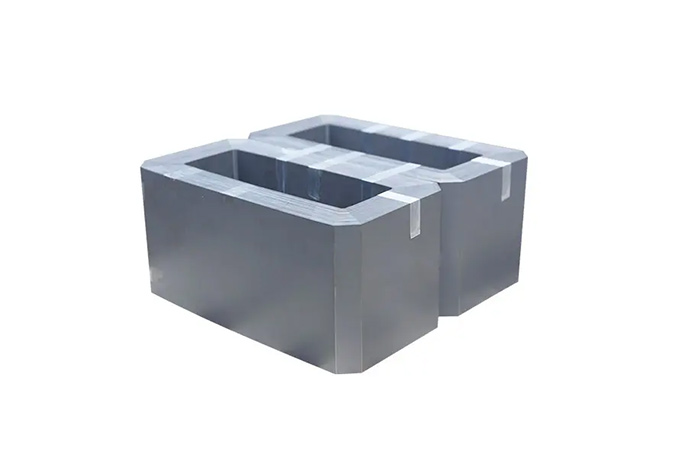
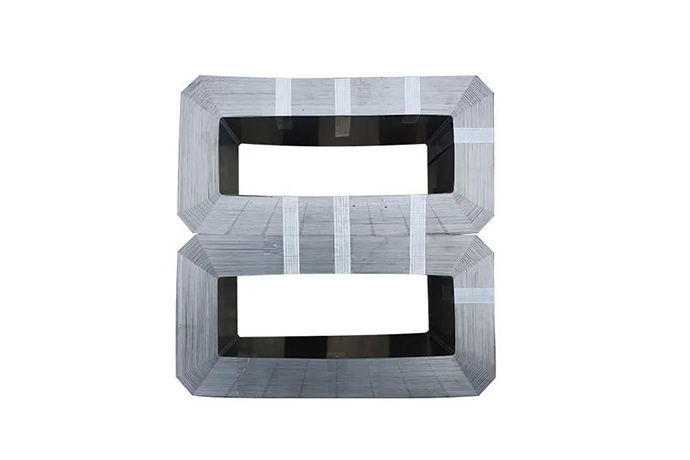
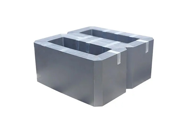
The core is constructed of electrical grade silicon steel, amorphous metal alloys, or nanocrystalline materials, stamped or wound into laminated stacks to reduce the loss caused by eddy currents. Applications of the core are in distribution transformers, power supplies, isolation transformers, and control transformers at industrial, commercial, and utility level electrical installations.
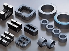
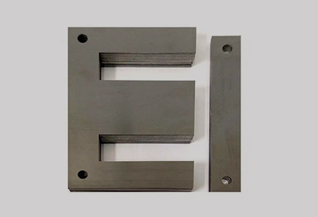
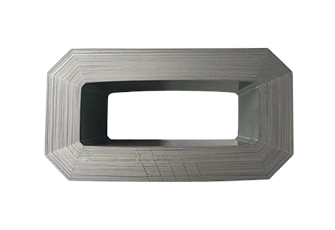
The core geometry ( E-I, E-E, toroidal, shell-type) defines flux density, leakage inductance, and thermal characteristics. The choice of core material and geometry is the single most engineering choice that influences the efficiency and operating cost of the transformer over a 20-40 year service life.
Its working principle is adopted by the electromagnetic induction. When AC current flows through the primary winding, the change magnetic flux inside the iron core coupled with the secondary winding, thus it induces an induced voltage of voltage ratio in the secondary winding. The function of the iron core is to constrain and focus the magnetic flux path for transmission of energy with minimum loss.
By optimizing the above structure and materials, more available energy is transmitted to the secondary circuit efficiently, then the temperature rise of the iron core can be effectively decreased, accordingly the no-load loss during the 24-hour continuous running of this equipment could be largely reduced and the lifetime of the transformer would be extended.
| Parameter | Value / Range |
| Core Material | Grain-oriented silicon steel (GOES), amorphous alloy, nanocrystalline |
| Lamination Thickness | 0.23 mm – 0.35 mm (silicon steel); 0.025 mm (amorphous) |
| Flux Density (Bmax) | 1.5 – 1.9 T (silicon steel); 1.3 – 1.56 T (amorphous) |
| Core Loss (at 1.7 T, 50 Hz) | 0.85 – 1.2 W/kg (GOES); 0.1 – 0.15 W/kg (amorphous) (verify with manufacturer) |
| Relative Permeability (µr) | 7,000 – 40,000 |
| Stacking Factor | 0.92 – 0.97 |
| Frequency Range | 50 Hz / 60 Hz; specialty types to 20 kHz |
| Operating Temperature | -40°C to +120°C (continuous) |
| Available Core Types | E-I, E-E, UI, Toroidal, Shell-type, C-core |
| Cross-Section Geometry | Square, rectangular, stepped |
| Standard VA Range | 25 VA – 2,500 kVA (verify with manufacturer) |
| Surface Finish / Insulation | Carlite coating, varnish, epoxy-coated laminations |

The single phase transformer core is designated whenever a single phase AC system demands efficient and reliable transformation of voltages. The choice of the core is dictated by its intended frequency, required flux density, thermal environment, and the efficiency class defined by the regional codes.
Typical applications include:
In terms of core type selection, different types are suitable for different scenarios:
The material decision should be furthered integrated by the application that specifically details the requiremets of the core:
For the customization of core specification, full parameter details are required to the supplier to ensure the core is designed and manufactured to satisfy the requirement including: rated power (V A/kVA), primary and secondary voltage, frequency, efficiency level (e.g. IEC level 2, DOE 2016), environment temperature, shell type and certification (UL, CSA, CE); for the customizing of special geometry, need to provide the bobbin or winding material, and some specific sizes of the bobbin or winding frame.
In the meantime, the minimum order quantity for customized lamination mould is generally less than 500-2000 pieces, which could be negotiated with the supplier depending on the core complexity.
| Feature | Single-Phase Core | Three-Phase Core |
| Construction | Single magnetic circuit | Three-limb or five-limb circuit |
| Application | Residential, single-phase utility, control circuits | Three-phase industrial power, motor drives |
| No-load loss per kVA | Higher at equivalent VA ratings | Lower due to shared flux path |
| Fault isolation | Simpler; failure affects one phase only | One core failure affects entire system |
| Cost | Lower for small ratings (<25 kVA) | More cost-effective above 25 kVA |
| Weight | Lighter at equivalent small ratings | Heavier, but more compact per kVA at scale |
| Availability | Standard and custom sizes widely available | Custom tooling often required below 10 kVA |
Single-phase cores are the correct specification for residential distribution, single-phase industrial control, and applications where load balancing across phases is not required. For three-phase grid infrastructure and motor-drive applications, three-phase core assemblies offer better economy.
IEC 60076-1 / IEC 60076-11
International standard for power transformer construction, test and performance. Outlines core loss measurements and temperature rise limits.
DOE 2016 Efficiency Standards(10 CFR Part 431)
The U. S. Department of Energy (DOE) requires minimum efficiency levels for distribution transformers. All amorphous cores meet or surpass the DOE‘s Tier 2 limits.
ANSI/IEEE C57.12.00
UL 506 / UL 5085
UL standards for specialty and low-voltage transformers respectively. Meets UL standards for use in North America for panel and control applications.
RoHS Directive (2011/65/EU)
Bans the use of certain hazardous substances in electrical equipment in the market place. Compliant cores made from silicon steel laminations and amorphous alloys adhere to RoHS standards.
CE Marking (Low Voltage Directive 2014/35/EU)
Applied to all transformer cores and assemblies sold within the European Economic Area.
ISO 9001:2015
Quality management certification at manufacturing level. Verifying consistent dimensional tolerancing, traceability of materials and process.