Three-phase Transformer Core

Three-phase Transformer Core

Material: High-grade CRGO silicon steel / Amorphous alloy
Thickness: 0.23 – 0.35 mm
Core Loss: Low loss ≤1.0 W/kg
Flux Density: Up to 1.7 T
Frequency: 50 / 60 Hz
Structure: Three-phase laminated core / Step-lap design
Capacity Range: 1 kVA – 10 MVA
Application: Distribution & Power Transformer
Share:

What Is a Three-phase Transformer Core?

A three phase transformer core is a three phase laminated magnetic path structure which supports the flux path of a three phase power transformer that has low reluctance, linking the primary and secondary windings. The core is the principal static component within any power transformer, forming the link between circuits by electromagnetic induction through the conductors. It affects the no load losses, magnetizing current, and acoustic noise.

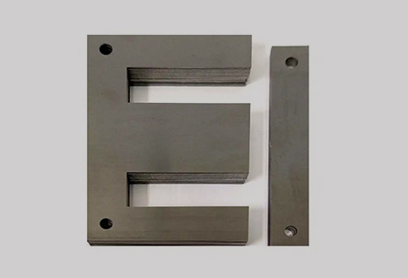
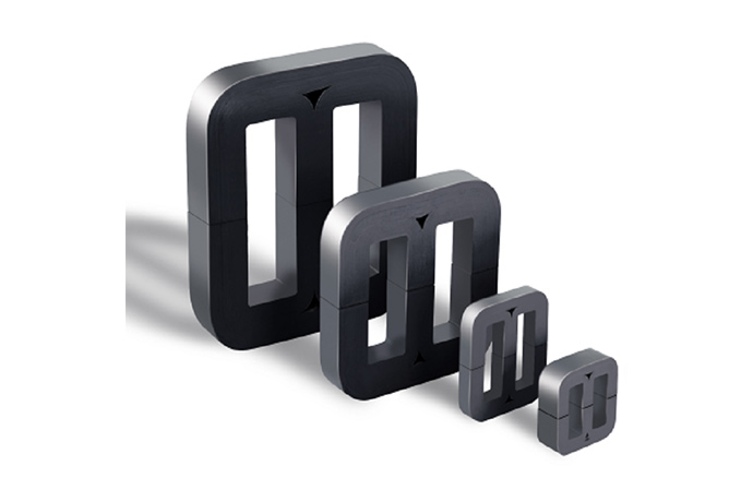
The core of a three phase transformer consists of a stack of individual thin electrical steel laminations coated in an insulating material. The laminations are cut, formed and stacked, creating either a three-limb or a five-limb core shape. The core is laminated in order to reduce eddy current losses to minimize circulating currents by limiting the cross sectional area. The quality of the core is the main contributor to efficiency, operating temperature and total lifetime cost of a transformer over its 30 – 40 year lifespan.

How a Three-phase Transformer Core Works

The three-phase transformer core operates on the principle of electromagnetic induction based on three magnetically coupled columns, and its core workflow is as follows:

  1. AC excitation: After the primary winding is energized with alternating current, it excites the magnetic flux that varies periodically with time within each core column;
  2. Flux path:the flux of each phase of the three-column core is returned through the adjacent core columns to complete the circuit, and the five-column core carries the zero-sequence flux through the two outer return columns to ensure stable flux conduction;
  3. Energy transmission:the secondary winding, which is co-wound with the primary winding in the same core column, couples the magnetic flux in the core and induces an output voltage proportional to the turns ratio of the winding, realizing the efficient transmission of electric energy;
  4. Loss control: Two types of losses are inherent in the core’s operation – hysteresis loss (energy loss due to repeated magnetization of steel) and eddy current loss (loss caused by circulating currents inside the laminated sheets), which can be minimized by using grain-orientated electrical steel and stepped-lap joint structure.

In addition, by strictly controlling the geometric precision of the joints and the stacking coefficient of the laminations, the excitation current can be further reduced, effectively suppressing the audible noise generated during the operation of the iron core and improving the stability of the equipment operation.

Key Specifications & Technical Parameters

ParameterValue / Range
Core MaterialGrain-oriented silicon steel (GOES) or amorphous alloy
Core Loss (W/kg)≤ 0.85–1.10 W/kg @ 1.5 T, 50 Hz (verify with manufacturer)
Peak Flux Density1.5–1.85 T (design-dependent)
Stacking Factor≥ 0.97
Operating Frequency50 Hz / 60 Hz
Insulation CoatingInorganic (C5), organic (C6), or semi-organic (specify grade)
Core Weight Range50 kg – 20,000 kg+ (custom)
Joint TypeStep-lap (preferred), butt-lap
Limb ConfigurationThree-limb, five-limb
Temperature ClassB (130°C), F (155°C), H (180°C)
Lamination Thickness0.23 mm, 0.27 mm, 0.30 mm, 0.35 mm

All values should be verified against your specific transformer design and confirmed with our engineering team.

Core Benefits

Ultra-low no-load losses
Construction of core by step-lap joint structures instead of butt-lap joint leads to 20% reduction in core losses, reduces the lifetime energy bill of transformers in distribution and power transformers.
High flux density capability
High grades of GOES are capable of conducting at 1.7 – 1.85 T without saturation, allowing for the design of more compact, portable cores.
Dimensional accuracy
CNC laser or guillotine-cut laminations are toleranced at +/- 0.1mm, to match on each stack to keep stacks and winding window dimensions constant throughout each batch.
Low acoustic noise
Acoustic noise of the material is reduced due to the optimized step lap geometry and maintained residual stress on the lamination surface, which reduces noise driven by magnetostriction by 3--6 dB compared to traditional stacked cores.
Full material traceability
Each core shipped with mill certificates with electrical steel, to give IEC 60076 type test documentation / qual audit data, and ISO 9001 audits.
Short lead time
Standardized profiles of the limb, pre-qualified steel inventory allow custom cores to be delivered in between 2 and 6 weeks depending on size and complexity.

RELIABLE QUALITY | BETTER PRICE | FASTER DELIVERY

One-stop transformer core solutions for bulk procurement: quality you can trust, costs you can save, and delivery you can count on.
Contact Us And You’ll Get:
Full Product Range:Comprehensive selection of transformer cores to cover all your industrial and power application needs.
Custom Design Flexibility: Quickly adapt core dimensions, materials, and performance to your exact project specifications.
Cost-Effective Bulk Supply: Factory-direct pricing for large orders, delivering superior value without compromising on quality.
Guaranteed On-Time Delivery: Adequate production capacity and efficient logistics ensure your bulk orders arrive when you need them.
Get Your Customized Quote
Consult Our Experts for Transformer Core Details & Solutions

    Applications & Use Cases

    Three-phase transformer cores are also offered for many other power and distribution applications, where the emphasis is on maximum efficiency, long-term reliability and tight dimensional tolerances. In addition to voltage class and rating, the core geometry and lamination grade have to be selected for each specific location of use.

    Common applications include:

    • Distribution transformers (10 kVA – 2,500kVA): Three-limb GOES cores have been used to manufacture pole-mounted and pad-mounted distribution service.
    • Power transformers (2.5 MVA – 500 MVA+):Five-limb cores for large generator step-up and substation autotransformers
    • Dry-type transformers (cast resin or VPI):Step-lap cores for industrial complexes, data centers, or commercial buildings
    • Traction transformers:High frequency design optimized cores for use in railways and metro traction applications
    • Rectifier transformers:Cores tolerant of high level of harmonic content when used in industrial drive and electrolysis applications.
    • Special-purpose transformers:Furnace, welding and earthing (grounding) transformer cores.
    • Renewable energy:offshore and onshore wind farm transformer cores intended for continuous operation in harsh environments

    Types of Three-phase Transformer Cores: A Comparison

    Choosing the appropriate core geometry involves comparing the advantages and disadvantages of three-limbs versus five-limbs, and core-form versus shell-form construction.

    FeatureThree-Limb CoreFive-Limb Core
    Transport heightHigher (no return limbs)Lower — suits large, tall units
    Zero-sequence impedanceHigh (balanced system)Low — needed for delta-free systems
    Material utilizationMore efficient~10–15% more steel required
    Preferred applicationDistribution, most power transformersLarge generator step-up, autotransformers
    Manufacturing complexityLowerHigher


    FeatureCore FormShell Form
    Winding accessibilityEasierRequires disassembly
    Short-circuit strengthLower inherentlyHigher — core surrounds winding
    Leakage flux controlStandardSuperior
    Preferred applicationDistribution, powerHigh-current, furnace, special purpose

    For most distribution and medium power applications, a three-limb, core form, step lap design employing grain-oriented silicon steel provides the optimum balance of cost,  performance and ease of manufacture.

    Lamination Materials: Grain-Oriented Silicon Steel vs. Amorphous Metal

    The lamination material is the single largest determinant of core loss.

    PropertyGrain-Oriented Silicon Steel (GOES)Amorphous Metal Alloy
    Core loss (W/kg @ 1.5 T, 50 Hz)0.85–1.100.10–0.20
    Flux density capability1.7–1.85 T1.3–1.56 T
    Material costBaseline3–5× higher
    Lamination thickness0.23–0.35 mm0.025–0.030 mm
    Handling / cuttingStandardBrittle — requires specialized tooling
    Best fitDistribution, power, tractionLow-loss distribution (TOD tariff regions)

    Owing to lower core cost and higher flux density capability, GOES continues to be the most popular core material for transformers above 500 kVA. For distribution transformers, Amorphous produces attractive efficiency improvements in transition loss tariffs scenarios at the cost of higher core cost and increased core volume.

    Customization Options & Buying Guide

    Three phase transformer core can be designed and specified in various configurations depending on the actual application requirements and transformer design; when asking for a quotation or specifying core requirements, the following parameters should be provided (to ensure the cost and requirement can be matched correctly):

    1. Geometric parameters

    Number of column (three-column/five-column, for transformer with different capacity); column diameter, cross-section shape (regular used round, cross); column height (the height of winding window, the same height of installed windings); yoke cross-section (equal cross-section/shrinking cross-section,  the accuracy for its performance and cost); particular size of core window (widthxheight, to find out the space of winding arrange).

    2. Magnetic parameters

    The optimum peak flux density at rated voltage (unit T,  influences the core saturation level risk); the working frequency (standard 50/60Hz, special condition should be given); the acceptable maximum no-load loss (W) or core loss density (W/kg), which should be satisfied by energy efficiency.

    3. Material selection

    Grain-oriented silicon steel (please specify grades, M4, 23ZH85 etc.); amorphous alloy; stack thickness ( conventional 0.23-0.35mm); level of insulation coating ( C5 inorganic, C6 organic etc to match the electrical insulation requirements).

    4. Manufacturing options

    Joint geometry (preferred ladder lap, lower loss)/butt lap; cutting pattern on the stacked sheets (slant cut/straight cut); Form of delivery (preassembled for ease of installation/bulked for ease of transportation).

    Compliance & Certifications

    Transformer cores designed for three phase use, according to the below standards are shipped with complete documentation.

    • IEC 60076 (Parts 1,7,10):International standard for power transformers covering losses, short-circuit withstand, and sound levels– all our cores are designed to enable full IEC 60076 type test compliance.
    • ASTM A876/EN 10107:Specifications for cold rolled grain-oriented electrical steel to magnetic characteristics and surface coating—all GOES laminations originate from certified mills.
    • ISO 9001:2015: Our quality system includes all stages of incoming steels inspection, lamination cutting, core assembly, and dimensional check.
    • RoHS Directive (2011/65/EU): Lamination insulation coatings avoid restriction of certain hazardous substances in electrical and electronic equipment.
    • REACH Regulation (EC 1907/2006): All goods are REACH compliant. Full declaration of substances is available upon request.

    Frequently Asked Questions

    Can you tell me the difference between a three limb and five limb transformer?
    A three-limb core contains three magnetic limbs—one per phase—with no separate return limbs and requires the outer limbs to return the adjacent phase flux. A five-limb core adds two outer return limbs, effectively decreasing the core height and permitting the use of zero-sequence flux paths. Five-limb cores are generally used for large power transformers where limits apply on the height of the transport.
    How do you measure the core loss of a three-phase transformer core?
    Core loss (also no-load loss) is the power supplied to the core when it is energized at the rated voltage and frequency, but with a secondary connection open circuited. The real power input is the total core loss in watts. Loss is given in terms of W/kg at a specific flux density -- usually 1.5 tesla at 50 Hz per IEC 60076-1 and IEC 60404-2.
    What are causes of acoustic noise in three phase transformer cores?
    Transformer core noise is the result of magnetostriction, or the dimensional variation of the lamination as the magnetic flux varies at 50 or 60 Hz in a cycle. The resulting audible fundamental frequency is twice the supply frequency or 100 or 120 Hz. Designing the transformer with step-lap joints, using controlled clamping pressure, and anti-vibration mounting systems, yields reductions in magnetostriction emmissions of several decibels over older stacking techniques.
    Why is grain-oriented silicon steel preferred over non-oriented steel for transformer cores?
    Grain-oriented silicon steel has its crysrtal structure oriented in the rolling direction, so is 3-5x lower in core loss than non-oriented steel in that direction. Transformer cores are designed so that flux flows along the rolling direction of the lamination. This results in core losses of 0.85-1.10 W/kg as opposed to 2.0-4.0 W/kg for non-oriented grades at the same flux density.
    What is step-lap joint construction and why is it significant?
    Stepper lap joint construction moves the overlap joints to a transformer core limb-to-yoke connection between lamination stack layers, passing the air gap over 5-7 steps, rather than one butt-lap interface. This results in a reduction of flux density peaks in the local joint in the core, leading to a decrease in the joint core loss of between 15 and 25 percent, and a reduction in the magnetostriction and audible noise levels over the conventional butt-lap cores.
    Can cores used in three-phase transformers be suited to unusual frequencies or voltage?
    Yes, three phase transformer cores can be built to operate over a broad range of frequencies from 16.7Hz (traction) to 400Hz (aerospace) and for any voltage class. The higher the operating frequency, the thinner the lamination required (0.10-0.23mm) and lower the flux density target for a given loss budget. Our engineering team will supply core designs tailored to your particular frequency, flux density and loss budget.
    sales@jinma-electric.com
    15093344253
    +86 15093344253
    Inquiry Now

      X