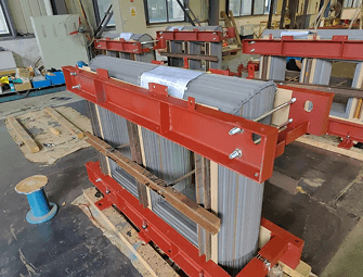
The transformer core is the magnetic heart of any electrical transformer. It is where the magnetic flux passes from the primary to the secondary winding, and by selecting the material and shape you decide how much energy is lost as heat, how big the unit has to be, and how long it will stay in operation.
Despite transformer core‘s importance, many misconceptions still remain. Engineers tend to blindly select traditional materials and neglect to consider whether other types of cores can significantly decrease losses, decrease size or decrease operating costs over the life of the product. Procurement teams find it difficult to compare specifications.
This guide simplifies the complicated. You will learn what the basic categories of transformer core are, how each operates, what applications they are most appropriate for, and the critical trade-offs that affect which core you should select. Be it a distribution transformer, switch-mode power supply, or accurate audio component, the proper core selection begins here.
What Is a Transformer Core and Why Does It Matter?
A transformer core is a usually- laminated (that is, formed of electro-magnetically permeable material, laminated together) magnetic circuit wound around by the primary and secondary windings. Its function is simply to focus and channel magnetic flux from circuit to circuit via electromagnetic induction.
Lack of core would mean these magnetic fluxes of the primary winding would escape into the surrounding air, this coupling is considered minimum, and not only would the losses be huge but the device would be massive, as modern analogy has it it‘s like going from a winding country road to an interstate highway iron core. The magnetic energy is faster, more effective and far more efficient.
The core affects three critical performance parameters:
- Core losses energy lost as heat in a transformer. This arises as a consequence of hysteresis and eddy currents.
- Magnetics coupling efficiency exactness to which flux couples primary and secondary.
- Saturation threshold of the flux density that is, the maximum flux density which the core can hold before the performance deteriorates.
These two parameters are the basis of any reasoned core purchase decision.
The Two Fundamental Construction Types: Core-Type vs. Shell-Type
Prior to introduction of the various materials, one must be aware of the two main types of geometry in transformer construction: the core-type and shell-type design.
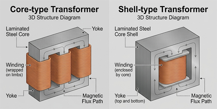
Core-Type Transformers
Core type Transformer The windings are positioned around the core of the transformer. The magnetic circuit runs through the middle of the arrangement and the coils are wound around the ‘arms’ of the magnetic core. Assemble and maintain is easier because of the more exposed surface area that is available for the radiation and the insulation can be applied more easily. Furthermore they are very mechanically stable, easier to operate at high voltages and easier to check on the field.
One disadvantage is that the magnetic coupling between the two coils is not as high as the shell-type construction due to the fact that the two windings are wound on different legs of the core. A small amount of flux will flow outside the core and this is termed as ” leakage flux”. For majority of applications of power transmission, this is considered as a reasonable compromise.
Shell-Type Transformers
The type shown is a shell-type transformer where the core is outside the windings. Both coils are wound on the same limb of the cross-section (a common middle limb); this means the two windings are as close as possible, increasing mutual coupling between the flux fields and reducing leakage flux. The middle limb generally has twice the cross-sectional area of the outer-legs giving the flux two closed paths.
Shell type construction is used in low voltage higher current specifications and provides much better mechanical strength, better natural cooling, better electromagnetic shielding etc. The only disadvantage of this type of construction is that the windings are not easily accessed for maintenance as they are covered with to the core construction.
Comparison at a glance:
| Feature | Core-Type | Shell-Type |
| Winding accessibility | Easy | Difficult |
| Leakage flux | Higher | Lower |
| Suitable voltage | High voltage | Low/medium voltage |
| Maintenance | Simpler | More complex |
| Mechanical strength | Good | Higher |
| Cooling | Air-cooled or oil | Natural convection |
The Main Transformer Core Materials
In both the core-type and shell-type design, the choice of core material governs the performance. Here is a list of the four major variations.
1. Laminated Silicon Steel Cores
The most common type of material for power and distribution transformers is laminated silicon steel. These stacks are composed of thin laminations of silicon- alloyed steel, usually 0.35 to 0.45mm in thickness, separated by an insulating coating.
The silicon content (usually 3–4.5%) greatly raises the electrical resistivity of the material which discourages the formation of eddy currents circulating within the core, generated by the time-changing magnetic field. The presence of eddy currents is a prime cause of loss in power and heat; by lamination, the path of the conductor is broken down.
Two sub-categories are worth distinguishing:
- Grain-Oriented Silicon Steel (GOES):The steel is rolled so the magnetic domains are all aligned in the rolling direction. This makes GOES have very high permeability in one direction, which is useful for transformer cores, as flux passes through a single fixed path. It is used in all large power transformers and distribution transformers.
- Non-Oriented Silicon Steel:Provides the same magnetic characteristics in all directions, and is more appropriate for rotating machine and some special application transformers. Usually has greater losses than GOES in addition to costing more.
Common core shapes using laminated steel include:
- E-I core:interleaved E-shaped steel sheets combined with I-shaped pieces. Cost-effective shape for manufacture. Commonly applied in small transformers or power suppliers.
- C-core (cut core):Formed when a steel strip is wound into a RECTANGULAR configuration, assembled in layers, then cut into two halves in the shape of a ‘C’. Since the flux always passes parallel to the grain direction, reluctance is decreased, increasing efficiency.
- U-I core:A U shape combined with a straight I shape. More effective magnetic coupling than an E-I core and commonly used in medium power transformers.
Suitable for: power transformers of 50/60 Hz, distribution transformers, isolation transformers, and other industrial installations.
2. Ferrite Cores
Ferrite cores are composed of a ceramic-like material where the compound is formed of an oxide of Iron (Fe O) with various metallic elements such as manganese, nickel, Zinc and Cobalt. Unlike the silicon steel they are completely non-conductive and as such a property such as exceedingly high electrical resistivity eliminates the problem of eddy current losses a property highly desirable at elevated frequencies.
Two major sub-types dominate the market:
- Mn-Zn Ferrites (Manganese- Zinc) have high magnetic permeabilities. It is used below 1MHz– Generally used in SMPS (Switch Mode Power Supply), TELECOM applications and medium frequency RF transformers.
- Ni-Zn Ferrites: lower permeability, higher resistivity. For use at frequencies > 1 MHz, where suppression of eddy currents is even more important.
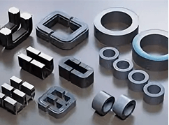
Ferrite cores are manufactured in many different shapes such as E-core, pot core, torroid and RM core. Different shapes are adapted for various winding arrangements and cooling requirements.
Main limitations of ferrite: brittle (it can crack under mechanical stress) and has a lower saturation flux density than silicon steel. Ferrite cores get very hot when approaching saturation.
Generally used for: power supplies operated in switch mode, telecommunication, RF unit, space at high frequency and so on. Additionally, it may be used for EMI filter or high frequency inverter. (Frequency: 10kHz-100MHz)
3. Toroidal Cores
A toroidal core is one that is wound in a toroid or donut shape, with a uniform distribution of turns around the whole circumference. The toroid is a special shape, as the magnetic path is through the centre of the toroid and forms a complete circuit with no breaks, which means little to no field radiates outward from the transformer. This therefore produces a very low level of EMI, ideal for high quality audio, medical and instrumentation use.
Many advantages are existing in toroidal transformer of silicon steel or permalloy strips as compared to similarly constructed E-I laminated transformer:
- Is approximately half the size and weight of a comparable E-I core transformer
- Reduced electromagnetic field emissions (roughly a tenth of E-1 types)
- Decreased mechanical hum important in audio amplifiers and precision measurement apparatus
- Reduce off-load losses so they are more efficient in standby circuits.
The strip-wound construction guarantees the grain boundaries are aligned efficiently in the flux flow path. The drawback for this construction is that the cost of fabrication is rather high (needs special winding machine) and the inrush current is a bit high (no air gap in the magnetic path).
Relatively low conducting ferrite toroidal cores are often employed in the frequency range of tens of KH z to hundreds of MH z, for their lower loss and small size.
Best for: audio amplifiers, medical equipment, precision instrumentation, low-EMI power supplies, and high end audio equipment.
4. Amorphous Metal Cores
Amorphous metal cores are the next step in transformer efficiency. The typical silicon steel has an ordered crystalline structure to its atoms. In amorphous metals, however, the metal is cooled so quickly that the atoms do not have the chance to form crystals, resulting in a “glassy” microstructure. These materials show a remarkable reduction in hysteresis losses: energy lost each time the magnetic domains in the core change direction.
Amorphous cores are produced by winding or stacking ultra-thin (often less than 25 m thick) metallic ribbon into the core shape. The combination of very thin laminations and low intrinsic hysteresis can yield a 70% reduction of core loss over normal silicon steel, 50/60 Hz – a mind boggling saving that is reflected in the reduction of the cost of power for the life of the transformer.
With ever tighter worldwide energy efficiency standards including the DOE 2016 and EU Tier 2 efficiency specifications amorphous core distribution transformers have become mainstream specification in many markets.
Nanocrystalline cores are an adjacent technology to amorphous, manufactured in the same way but heat-treated to produce a partially crystalline structure. They can have saturation flux densities even higher than the amorphous metals which makes them useful for efficient operation with high magnetic fields such as high frequency inverters and power factor correction circuits.
Suitable for: Energy-efficient distribution transformers, Power grids modernization, Renewable energy sources, Solar inverters, Wind turbines, Wherever there is a need to reduce no-load losses.
5. Air Cores
Air core transformers use no solid magnetic core material. The primary and secondary windings are wound on a non-magnetic former and the air itself is the medium of flux. As there is no ferromagnetic core material to approach saturation or have hysterisis losses there is a very wide range of possible frequencies at which such a device can operate. For example to radio frequencies.
Furthermore, the lack of core substances removes all of these core related non-linearities, so air core transformers are commonly used in high definition signals. Due to the extremely low magnetic permeability of air, compared to ferrite of steel, air core inductors require far more turns to achieve a given inductance. This makes air core transformers physically larger and heavier, and less efficient at lower frequencies.
Ideally suited for: RF circuitry, radio transmitters, some audio applications and wireless power transfer.
Core Shapes: How Geometry Affects Performance
In addition to the type of material used, the shape of the transformer core can affect its efficiency, the properties of its windings and its usefulness for different applications. These are the most frequently found shapes:
- E-I Core: Best for low- to medium-power applications. Cheap, easy to wind, higher leakage flux.
- C-Core / Cut Core: Better flux alignment than E-I; used in precision and audio transformers.
- Toroidal (Ring) Core: Usually available in higher frequencies. No air gaps give less leakage flux, low EMI, and small size but cost is higher to wind.
- U-I Core: Better coupling than E-I; used in inductors and medium-power transformers.
- Shell Core: Contains windings for powerful magnetic shielding. Suitable for heavier loading industrial use.
- Encloses the entire winding (pot core) and offers the best EMI shielding (used in hifi high frequency applications).
How to Choose the Right Transformer Core: Key Decision Factors
Selecting the right transformer core requires balancing several interdependent variables:
1. Operating Frequency
This is usually the filter‘s most important working frequency. Laminated silicon steel shows very low losses at 50/60 Hz but will rapidly increase in losses once the frequency exceeds a few kHz. Ferrite & amorphous materials will be necessary once the frequency enters the 10‘s of KHz & above. For RF in the MHz range the correct choices of ferrite Ni-Zn grades, Air Cores etc. should be used.
2. Power Level/Size and Physical Size
Laminated silicon steel scales well to hi power levels. Also Ferrite cores are small and efficient but have a lower saturation flux density, and if not sized correctly they will tend to saturate and overheat under heavy loads. Check the flux density at peak load.
3. Efficiency Requirements
If saving no-load losses is important whether they are useful: for active equipment, or not useful: for always-on equipment or economies of scale transformers the amorphous cores are able to amortize their premium by saving energy in the long term. The savings can be quite significant over the course of a 20–30 year transformer lifetime.
4. EMI Sensitivity
When used in proximity to sensitive electronics and medical or audio equipment, the low stray field emissions associated with toroidal cores often make the higher manufacturing cost more than justified.
5. Environment and mechanical constraints
Most ferrite cores are fairly brittle, so if the application involves vibration or mechanical stress laminated steel or amorphous wound cores are better options. Toroidal cores are the smallest size, and also allow single bolt mounting which may be easier to fit in small enclosures.
Transformer Core Losses: Understanding the Two Main Sources
Regardless of core type, energy losses within the core fall into two categories:
Because the magnetic domains in the core material have to be reorientated with each reversal of the alternating magnetic field. Each reorientation consumes a little energy which is lost as heat. The greater the area enclosed by the B-H (flux-magnetising force) hysteresis loop, the greater the loss per cycle. Narrow hysteresis loops (grain-oriented silicon steel and amorphous metals) reduce the amount of hysteresis loss.
Eddy Current Loss arises due to circulating electrical currents, induced in the conducting core material by the changing magnetic flux. The circulating currents deposit heat and oppose the main magnetic field. Laminating the core (and using high resistivity conductors such as silicon steel or ferrite) chops up the conducting paths, and reduces eddy currents.
Hysteresis and eddy current losses are collectively core or no-load loss that is, they exist all the time, no matter whether a load is being supplied or not. For example, a large distribution transformer running 8760 hours a year; a 1% saving in no load losses can make dramatic saving in term of energy and money.
Application Quick Reference Table
| Application | Recommended Core Type | Reason |
| Power distribution (50/60 Hz) | Laminated silicon steel | High efficiency, low cost, proven reliability |
| Switch-mode power supplies | Ferrite (Mn-Zn or Ni-Zn) | Low eddy current losses at high frequencies |
| Audio amplifiers | Toroidal or nickel-iron | Ultra-low EMI, minimal hum, clean signal |
| High-efficiency grid transformers | Amorphous metal | Up to 70% lower no-load losses vs. silicon steel |
| RF / telecommunications | Ferrite or air core | Low losses at MHz range frequencies |
| Medical / instrumentation | Toroidal | Minimal stray fields, precision performance |
| Renewable energy inverters | Amorphous or nanocrystalline | High efficiency, high switching frequency |
Frequently Asked Questions
Q: What is the most common transformer core material?
A: Laminated silicon steel is the world‘s most common material for transformer cores. It is an optimal compromise between magnetic performance, mechanical strength, and cost of manufacture and is chosen as the standard core material for power & distribution transformers operating at utility frequencies (50 or 60 Hz).
Q: How do you differentiate a core-type with shell-type transformer?
A: When the windings are around the core, it is a core-type transformer. However, the windings are around the core in a shell-type transformer. It also has lower leakage flux and superior magnetic shielding but the windings are difficult to access. It is easier to assemble and inspect and is used predominantly in high-voltage applications.
Q: Why is the core of a transformer made of laminated iron rather than a single solid piece?
A: Electromagnetic induction induces currents in everything, and the current field is limited because of the resistive nature of the material. But makes the circumference of the field bigger, increases the energy loss from a transformer. Laminations (many thin sheets of insulated iron instead of one big piece) break up the pathways for the induced currents and so prevent them from circulating around the whole core, which would cause lots of heat to be produced and a lot of wasted energy. This is one of the most well-known methods for reducing core losses.
Q: How do I select a ferrite core as opposed to silicon steel?
A: Select a ferrite core for any application where the frequency is higher than about 1–10 kHz. The excellent electrical resistivity of ferrite means that it will not suffer from excessive eddy current losses in that range, unlike silicon steel. Ferrite is the all-round choice for switch-mode power supplies and RF transformers, as well as telecommunications equipment.
Q: Are amorphous core still cost effective?
- When a distribution transformer is permanently energized the amorphous core advantage of 70% or more lower no load losses over the traditional silicon steel can be more than repaid in terms of energy savings over a 20 30 year life. They are also becoming a standard requirement for the latest EE standards.
Q: Which core type is most suitable for reducing EMI?
A: Toroidal cores have the least amount of stray magnetic field of any transformer design. In fact, they generate roughly 1/10 the external field of an equivalent E-I laminated core construction. For this reason, they are generally used for audio amplifiers, medical instruments, and any other device where electromagnetic interference is undesirable.
Conclusion
The choice of what type of transformer core to use is one of the most important considerations in designing and buying a transformer. It affects efficiency and size; it influences heat production and electromagnetic emissions; it affects ongoing maintenance costs but most importantly it effects just about everything else that ‘counts’ about the way a transformer works in practice.
To summarize the key principles:
- Laminated silicon steel is a proven, low-cost solution for 50/60 Hz power applications.
- Ferrite cores are generally used as the standard material for high-frequency power electronic design where the eddy current losses are essentially zero.
- Nothing beats toroids for the lowest EMI and the most accurate sound.
- Modern developments of amorphous and nanocrystalline core materials offer the maximum energy savings and the minimum carbon footprint.
No one core type rules all. The best decision is based on an unbiased evaluation of operating frequency, power level, efficiency goals, EMI constraints, and TCO. With the toolkit provided in this guide, you will be prepared to make that assessment.