Each voltage flows along dozens of transformers from the local power plant to your building. While most engineers and purchasing managers don‘t look beyond what makeup the core of those transformers: the core.
The transformer core is not merely a solid block of metal. It is an active magnetic circuit that makes any voltage transformation a reality. If correctly executed, you‘ll have a transformer that runs silently, nearly energy efficient, and is good for twenty odd years. Otherwise, you‘ll be paying the price in energy losses, electricity bills, and equipment breakdowns.
As the U. S. Department of Energy wraps up new efficiency standards with an implementation date of April 2024 standards that are predicted to generate over $14 billion in savings in energy costs over the next three decades transformer core choice has never been more important for industrial and utility purchaser. This how-to covers exactly what a transformer core is, how a transformer core functions, what type and materials are available, and how to select the appropriate core for your needs.
What Is a Transformer Core?
![]()
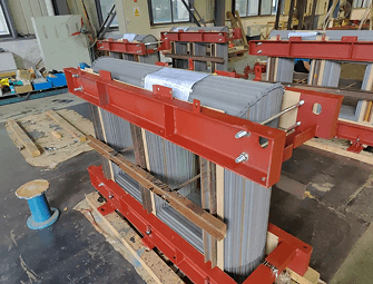
The nature of a transformer core is a building block for the magnetic circuit, normally formed of thin, laminations of ferrous metal about which the primary and secondary windings are wound. Its only purpose is to give a path of low reluctance for the magnetic flux produced by the primary winding, such that all the flux passes through the secondary winding as much as possible.
Put plainly: the core is the bridge that takes power from one bank of coils to the other. (That is, there is no electrical connection via the core)
Otherwise, without that core, the flux generated by primary coil simply would have gone falling off into the surrounding air. You would have lost the vast majority of your energy long before it reached the secondary winding. (And as it happens, the core helps you concentrate and channel that flux, allowing you to do voltage transformation efficiently.)
The transformer cores consist of a series of limb s, around which the coils are wound, and yoke s, which are the horizontal parts. The combination of yokes and limbs form a closed magnetic circuit, which is similar to a closed electrical circuit.
How Transformer Core works?
In order to understand the working of a transformer core, first you need to understand the concepts behind it that is: electromagnetism which is explained by Faraday‘s Law.
Here is the step-by-step sequence:
- The alternating current (AC).This creates a magnetic field which varies constantly around the coil.
- The magnetic flux enters the core. As the core is made of very permeable material, the flux prefers to travel through the core rather than diverge into the air.
- Flux passes around the closed magnetic circuit. The laminated core directs flux through the limbs and yoke keeping the magnetic field under tight control.
- The flux changing through the secondary winding.This changing magnetic field induces a voltage in any conductor which it passes through according to Faraday‘s Law.
- Voltage is induced in the secondary coil.V 2 / V 1 = N 2 / N 1.
Core does not carry any electrical current and produces no energy. It just directs magnetic energy. The difference appears in how good the core is, some magnetic energy is lost into heat and not delivered to the load.
Core Losses: Where Energy Goes
Two unavoidable loss mechanisms occur within every transformer core:
- Hysterisis losses: As the magnetic domains of the core material are rotated backwards and forwards due to the reversing of the AC fields. Energy is used each cycle to “flip” the domains. Material with a high permeability, for example grain oriented silicon steel, are used to reduce hysterisis losses as they require less energy every time a domain is flipped.
- Eddy current losses: current circulating in the core itself, induced by the changing magnetic field. The current heats up the core. The most common solution to this problem is to lamina the core by stuffing it with a number of thin electrically insulated sheets ( order of 0.25-0.5 mm thick). This prevents the eddy currents from forming a large loop.
When combined, these losses go under the field loss or no-load losses, since they can be experienced even when no load is being supplied by the transformer but the transformer is energized. Reduction of these losses forms the primary engineering aspect of core design.
Transformer Core Materials: Silicon Steel, Amorphous, and Ferrite
Perhaps the most crucial decision in designing a transformer is selecting the core material. The modern-day designing of transformers has three main families of materials:
Grain-Oriented Electrical Steel (GOES / Silicon Steel)
The workhorse for industry is grain oriented electrical steel. Since silicon (usually around 3% by mass) increases a steel‘s electrical resistivity, it is added, thereby significantly lowering eddy currents in the material. Additionally, the steel is rolled until the grain structure is oriented in the material‘s rolling direction, this further improves the permeability and consequently reduces hysteresis and eddy current losses.
GOES is the traditional core material of medium-and high-voltage power and distribution transformers. It has an attractive profile of low cost, familiarity, high mechanical strength, and American manufacturing. Confirming the Department of Energy‘s 2024 final rule, about 75% of distribution transformer cores will remain to use GOES to meet the new efficiency standards –… proof that global supply disruptions hasn‘t damaged domestic supply chain resilience(29).
Amorphous Metal (Amorphous Steel / Metallic Glass)
Amorphous metals are made by the rapid solidification of molten alloy in a quench where the speed is high enough to prevent the atoms from forming a crystalline array. The amorphous non-crystalline arrangement of atoms produces very low hysteresis and eddy current losses a lot lower than silicon steel, generally 60-70% reduction.
Such benefits make amorphous cores appealing for 24/7 operation distribution transformers, in which no-load power losses are accumulated steadily. The worldwide market for amorphous-core transformers was worth $4.1 billion in 2024 and is expected to reach a CAGR of 8.6% by 2033, as global efficiency standards mature.
The tradeoff: amorphous steel cores are more expensive before use, are mechanically less resilient, and supply chains are much tighter. The DOE‘s 2024 rulemaking was influenced in part by the fact that the U. S. Only has one domestic amorphous steel supplier Metglas, in Conway, South Carolina.
Ferrite Cores
Ferrite cores are ceramic compounds consisting of varying proportions of iron oxide and a metallic element such as zinc, nickel or manganese. Their main property is the very high electrical resistivity, which prevents the occurrence of eddy currents (at high frequencies) without the requirement of a lamination.
To this end, ferrites are the we expect to use in all high-frequency situations: switch-mode power supplies, phone chargers, adapters for laptops, inverters, and used in other telecommuncations equipment. They are extremely bad for low frequency (50/60 Hz) power distribution, where ferrites saturate at too low a flux density for whatever you want to do. But in the kilohertz-to-megahertz range, ferrite is king.
Transformer Core Types: Core-Type vs. Shell-Type
Apart from construction materials, the core structure also affects performance, accessibility for maintenance and application:
Core-Type Configuration
In a core-type transformer, the windings are a round the core. The coils sit on different limbs of the core construction. This design features:
- More appropriate for high-voltage, high-power utilization physical separation of windings can help manage insulation more effectively.
- Simpler access to maintain since the windings are on the outside of the core, they can be easily examined and changed without removing the whole core.
- Increased copper usage separately wound placement needs extra conductor material.
- A little increased leakage flux due to the windings being less tightly coupled.
Most new large power and distribution transformers used by utilities have core-type construction.
Shell-Type Configuration
In a shell-type transformer the core encircles the windings. The magnetic circuit “wraps around” the coils: These advantages are:
- Increased magnetic coupling — the windings are more fully enclosed and less flux is leaking away.
- Superior thermal management several flux paths spread heat out more efficiently.
- More compact form factor – shells are generally more compact than their equivalent power rating.
- More complicated maintenance access to the windings will need to be made by removal of the core.
Connection type: The shell-type configuration is widely used in audio transformers, furnace transformers and high-current industrial applications, but has limited use now a days and is being adopted in the modular & hybrid type of transformers for smart grid application.
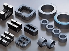
Core Shapes: E-I, Toroidal, C-Core, and More
The physical geometry of the core laminations affects the efficiency, leakage, ease of assembly and volume required. The most common designs are:
E-I Cores are made up of E-shaped and I-shaped laminations and are the most common core shape for distribution and small-to-medium power transformers. They are relatively easy to assemble and perform well over a wide range of power levels.
Toroidal Cores are you guessed it doughnut shaped? These types of cores are wound from a solitary strip of material, which has many advantages. Toroids generate extremely low leakage, have low acoustic noise, and are small in size. These characteristics make toroids very frequent in audio equipment, medical devices, and precision instruments.
C-Cores are produced by winding a strip of steel into a coil and cutting it in a C shape, they are very easy to assemble around pre wound coils and generate less leakage flux and therefore are often found in audio transformers and high frequency coil.
U-I Cores employ the use of I-shaped and U-shaped laminations and are quite prevalent in medium-power applications where the windings fit naturally into the U-shape.
Each core design implies a compromise between efficiency, leakage, fabrication costs and application suitability. For high performance applications, choice of core geometry should be part of the engineering specification not an afterthought.
Core Construction: Lamination, Stacking, and Assembly
A knowledge of transformer core construction allows engineering and procurement to effectively assess claims about quality from suppliers.
The lamination thickness of conventional silicon steel cores varies from 0.25 mm to 0.5 mm. The thinner the lamination, the lower the eddy current losses. However, it becomes more costly and difficult to manufacture with thin laminations. High efficiency cores used in present-day distribution transformers often employ 0.27 mm or 0.23 mm laminations, which is a specification value that affects no load losses and would be shown on most transformer specification sheets.
Insulation between the laminations is a very thin coating of insulating varnish or oxide on each sheet. It is the electrical insulations which blocks eddy currents from passing through the entire cross-sectional area of the core. If the insulation breaks down localised temperature peaks can be generated and the apparatus may fail early; hence it is checked for during transformer inspection and commissioning.
Mitre-cut versus butt-stacked is a significant differentiator. In mitre-cut cores the laminations are cut at 45o angles on the corners so as the flux hits the bend it can follow the steel grain direction. This prevents the grain-crossing which occurs at the butt-jointed joints and can be seen in the performance tests as consistently lower no load losses.
Distribution gap cores (wound cores) are formed by winding the steel strip into a coil, rather than stacking individual laminations. Bynothaving joints at sharp corner locations, flux distribution is very uniform and losses are minimized. Almost all distribution transformers in the U. S. Are built using a distributed gap core construction.
Core Losses, Efficiency, and the Cost of Getting It Wrong
Efficiency of a transformer is defined as Power delivered divided by Power consumed. Present day distribution transformers have the efficiencies of 98 99% but that 1 2% power losses, when consumed for 24 hours in a day, 365 days in a year, over a period of 30 40 years makes a lot of operating cost, over time.
Core loss is the most costly kind of loss, as it is continuously present. Even a 10% load transformer is still giving off its full no-load core losses. This is why of all the losses on the nameplate, utility operators and large industrial consumers are most anxious about the no-load loss figure. The nameplate kVA rating states what the transformer can do at maximum load; the no-load loss figure states what it‘s costing you every hour it is running.
According to the U. S. DOE, if the efficiency of transformer cores across the entire nation-wide distribution fleet were enhanced, the cumulative energy consumption would be diminished by 4.6 quadrillion BTU over the equivalent of 30 years (a 10% decrease as compared with competitive products already available). That amount of savings points to decreased electrical bills for all commercial and industrial consumers in the country.
For B2B buyers, use the no-load loss specification (in watts) as a top procurement rule alongside nameplate capacity. To ensure good responses, specify that suppliers submit certified test data instead of catalog estimates, and calculate the lifecycle cost differential between rival core materials based on your actual load profile and rate.
Transformer Cores in the Renewable Energy Era
Transmission and distribution grids’ integration of wind, solar and distributed energy storage will require transformer core design changes. Formerly, the flow of power from large, centralized sources to load centers was solely from the load to the source. Today‘s grid needs to push power back from solar and storage uses, variable frequency, and smaller size for limited urban/ offshore location.
Amorphous and nanocrystalline cores have seen growth in renewable applications because their lower loss characteristics offer an advantage as transformers need to operate as efficiently as possible during fluctuating generation. The DOE‘s 2024 efficiency rulemaking cites EV charging infrastructure and data center expansion directly as the market emergence drivers – both utilize high throughput infrastructure, where core loss efficiency impacts operating cost.
The new and improved standards from the DOE by 2028 will force manufacturers to strive for the new, far tighter, efficiency levels. And the writing is on the wall for procurement departments: the transformers being bought today for a 30 years of service are going to be operating in a regulatory environment that is progressively leaning toward novel core materials and more stringent loss specifications.
How to Choose the Right Transformer Core for Your Application
The critical parameters to consider when selecting a transformer core are the various material properties, core configuration, construction method, and your application. The following matrix provides a rough guide:
- Identify your frequency bandwidth. Typical 50/60 Hz power distribution-> silicon steel or amorphous. High-frequency switching (kHz+)-> ferrite or nanocrystalline.
- Identify your loss budget.Figure the no-load loss costs for the expected service life of the transformer (usually 20–40 years) based on your local electricity rate. This cost usually makes a higher-efficiency and more expensive core material cost-effective.
- Think about duty cycle. A transformer that is running all the time at a fairly low load would get the greatest benefit from having very low no load losses (amorphous advantage). A transformer that is running most of the time at a very high load should try to optimize a balance of coreloss and loadloss.
- Check regulation requirements. Should the transformer be installed in USA after April 2029, it will be necessary to meet DOE 2024 efficiency standard. As it should be specified, check if your supplier‘s equipment will be compliant.
- Consider the total cost of ownership.Amorphous cores are more expensive initially but usually recoup the cost in energy savings within 3–7 years, depending on load profile and electricity prices. Ask your transformer supplier for a lifecycle cost analysis.
- Verify the core specs.Demand that vendors submit certified test data for no-load losses, core loss watts per kG, and lamination grade. Do not depend solely on catalog specs.
Frequently Asked Questions
Q: What does a transformer core do?
A: The function of a transformer core is to offer a low-reluctance path for the magnetic flux created from the primary winding. This supports the magnetic field to connect the primary and secondary windings so that the energy can be transferred from one to the other via the magnetic flux using electromagnetic induction.
Q: If the core were make from a solid section of steel why would this be inappropriate?
A: A solid conductor would have large eddy currents flowing through the back, creating a lot of heat, which is inefficient. By using a stack of thin ferrous laminations, with both faces insulated, the eddy currents are confined to loops within each element, greatly reducing the severity of the eddy current loss.
Q: What‘s the difference between a core type and a shell type transformer?
A: In a core type transformer the winding surrounds the outside of the core ‘legs’, whereas with a shell type it is the other way around; the magnetic core surrounds and encloses the winding.
Q: What are core losses and why do they happen?
A: When the AC supply is constantly changing in direction, the magnetic elements within the core have to be re-magnetized each time to a different polarity. This consumes energy which needs to be supplied from the power source each time the change occurs. (the material is made to use as little energy for every change of magnetization as possible, such high quality core materials are called grain oriented silicon steel or amorphous metal.)
Q: What are the revised DOE 2024 transformer efficiency standards?
A: The US DOE in April 2024 finalized revised energy efficiency standards for distribution transformers which become fully effective in April 2029. As a result, about 75% of distribution transformer cores will still be produced with grain-oriented electrical steel (GOES) and some of the market will be switching to amorphous alloy cores. According to estimates, this will save about $824 million per year in U. S. Electric costs and reduce carbon emissions by almost 85 million metric tons, over a period of 30 years.
Q: Is the higher cost of amorphous core transformers justified?
A: Amorhphous cores are generally cost-effective compared to silicon steel cores when used for continuous operation at low-to-medium load, like distribution transformers serving residential and commercial loads. The reduced no-load losses are usually 60–70% less than silicon steel cores and the energy savings over a 30–40-year service life will generally out-weigh the initial cost premium. payback period will be different depending on local electrical rates and average load factor.
Conclusion
The world’s power grid relies on the transformer core. While it does no apparent work, consumes no electricity, and (assuming good design) makes no noise in its absence every bit of electrical energy transferred between voltage levels would be physically impossible. The less power wasted as heat flowing between the generator and your plant, the more power you use.
Transformers’ Cores For B2B purchasers, engineering teams and utility buying groups, transformer cores are certainly second to none anymore. With DOE 2024 efficiency standards emerging in, crumbling infrastructure and need for replacement for the United States, as well as the transformation of the power flows implied by renewable energy policies, the transformer core is surely situated in one of the decade’s most significant infrastructure investment decisions.
Preparing to pick the perfect transformer core? Work with our engineering team for a no-load loss comparison by core material, a total cost of ownership comparison by core material, or DOE 2029 fleet compliance advice.