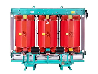


What Is Transformer Core Saturation?
Transformers work on the basis of electromagnetic induction: After the primary winding is energized, an alternating magnetic field is generated in the iron core, coupling the energy to the secondary winding.
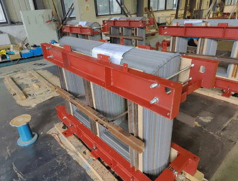
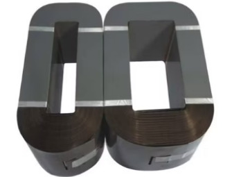
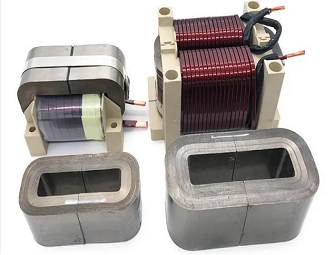
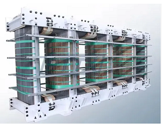
Iron core by silicon steel sheet, amorphous alloy, ferrite and other ferromagnetic materials stacked and become, the role is to concentrate the magnetic circuit, reduce the magnetic resistance, enhance the coupling efficiency.
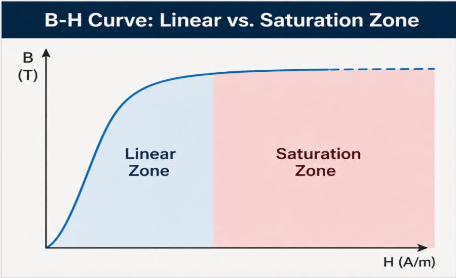
Iron core saturation, simply put: Magnetic flux density of the iron core has reached the upper limit, and can no longer be synchronized with the increase in excitation current. During normal operation, the excitation current rises slightly and the magnetic flux rises sharply, which is the linear working area of the iron core with the highest efficiency and lowest loss. When the magnetic flux exceeds the material critical value, the B-H curve enters the flat section, and then increase the excitation current, the magnetic flux almost no longer grows, the iron core into the deep saturation state. At this time, the core equivalent permeability plummeted, close to the air permeability, the transformer from the “high efficiency magnetic coupling device” into “low inductive reactance resistor device”, a series of malignant failures then broke out.
Common Causes of Saturation
Overvoltage
Voltage is positively correlated with the magnetic flux of the iron core, and operation voltage exceeding the rated value by 5% can break the iron core saturation threshold. Grid daily voltage fluctuations, lightning surge impact, reactive power compensation switching, high-power equipment start and stop and other persistent over-voltage or transient spike over-voltage, will continue to compress the iron core safety margin, is the most important reason to induce iron core saturation.
Frequency mismatch
Iron core flux and operating frequency is inversely proportional to the low-frequency conditions will significantly increase the flux density, it is very easy to trigger the steady state saturation. In the project, 60Hz transformer is directly connected to 50Hz power grid, which will greatly increase the magnetic flux and exhaust the design margin; frequency drive equipment, diesel generator, aviation high-frequency power supply and other non-standard power supply scenarios there is a frequency drift problem, so that the transformer is in the saturation of the high-risk conditions for a long time.
DC bias
Weak DC current will offset the core B-H magnetization curve work point, destroying the balance of positive and negative half-week magnetization conditions, triggering typical half-wave saturation. Rectifier ripple, new energy inverter DC leakage, system ground loop current, geomagnetic disturbance, power electronic devices asymmetric conduction, etc., will introduce DC interference, resulting in localized overheating of the transformer, harmonic overload.
Excitation inrush current
Transformer no-load switching operation, the core residual residual magnetism and newborn alternating flux superposition, instantaneous flux density rises dramatically, triggering the depth of saturation. The resulting large excitation current will dramatically increase the winding copper loss, resulting in local overheating, insulation aging, frequent closing shock will also damage the core and winding structure.
High temperature environment
Ferromagnetic iron core material has temperature sensitivity, temperature rise will directly reduce the saturation flux threshold, compression anti-saturation safety margin. Transformer long-term overload, winding heat, the installation environment of airtight ventilation is poor, high temperature in summer sunshine and other conditions, will cause the equipment temperature rise exceeds the standard, so that the normal operating flux indirectly exceeds the limit, quietly induced iron core saturation.
Design inherent defects
Some manufacturers deliberately reduce the effective cross-sectional area of the iron core to control production costs, or the design stage is not reserved for voltage fluctuations, short-term overload safety margin, resulting in high magnetic flux density per unit area, the transformer inherent anti-saturation capability is insufficient, the conventional rated operating conditions will be in a long time in the critical saturated state, prone to heat, saturation potential problems.
Why Core Saturation Is Dangerous
Dramatic increase in excitation current, burning the winding insulation
Iron core saturation excitation current peak can reach 10 ~ 50 times the rated current, the winding copper loss increases dramatically, the temperature rises rapidly, resulting in insulation softening, aging and even breakdown, very easy to trigger turn-to-turn short-circuit, ground breakdown, direct damage to the transformer body.
Iron loss copper loss surge, there is a thermal runaway security risks
Saturation hysteresis loss, eddy current loss synchronous rise, superimposed on the winding of high current copper loss, the equipment produces a large number of local hot spots, accelerate the insulation material and transformer oil degradation. If you fail to protect the shutdown in time, it is easy to cause equipment thermal runaway, and even fire, box burst and other serious accidents.
Serious waveform distortion, inducing harmonic pollution and chain failure
Nonlinear characteristic of iron core saturation will produce a large number of 3, 5, 7 odd harmonics, seriously degrading power quality. Harmonics will cause the back-end power equipment heating degradation, interference relay protection error or refusal to act, the third harmonic formation of zero-sequence loop current will also lead to zero line overload, triggering low-voltage power distribution system failure.
Increased electromagnetic vibration, accelerate the aging of equipment mechanical structure
Saturation generates intense alternating electromagnetic field, so that the core stack high frequency vibration, operation noise exceeds the standard. Long-term vibration will cause winding loosening, poor lead contact, iron core stacked piece of misalignment wear, equipment fasteners loose, fatigue tank cracking oil leakage, significantly shorten the service life of the equipment.
Voltage stabilization and regulation failure, easy to induce large-scale failure at the grid level
Iron core saturation destroys the electromagnetic balance of the transformer and transformer capacity, voltage regulator failure, secondary side voltage distortion, fluctuation is serious. Once the main transformer saturated, it is easy to trigger regional voltage disorder, protection chain tripping, resulting in large-scale power outages, bulk equipment damage, a serious threat to the safe and stable operation of the power system.
Select the Right Core Material
Following table is a reference for engineering selection criteria:
| Material Type
| Saturation flux Bₛₐₜ(T) | Applicable Frequency
| Iron Core Loss
| Cost | Typical Application
| Core Advantages
| Shortcomings
|
| Cold Rolled Silicon Steel
| 1.8–2.0 | 50–400Hz | Moderate
| Low | Distribution Transformers, Power Transformers
| High Saturation Flux, Cheap and Durable
| High Frequency Loss
|
| Amorphous Alloy
| 1.4–1.6 | 50Hz–10kHz | Extremely Low
| Mid-to-High
| High-efficiency Distribution Transformers, Photovoltaic Inverters
| Ultra-low Loss and Energy Saving
| High brittleness, low Bₛₐₜ
|
| Nanocrystal
| 1.2–1.4 | 1kHz–500kHz | Extremely Low
| High | High Frequency Power Supplies, Transformers
| Ultra-High PermeAbility, Low Loss
| High Prices
|
| MnZn Ferrite
| 0.4–0.5 | 10kHz–1MHz | Lower
| Mid-to-Low
| Switching Power Supply, SMPS
| High Impedance, Low Cost
| BₛₐₜExtremely Low, Temperature Sensitive
|
| NiZn Ferrite | 0.3–0.4 | 1MHz–100MHz | Lower
| Center
| RF Variable, High-Frequency Signals
| Ultra High Resistivity
| Very Low Saturation Flux
|
| Iron Powder Core
| 0.6–1.2 | 100Hz–500kHz | Mid-to-High
| Center
| Inductance, Flyback
| Distributed Air Gap, DC Resistant
| High Loss
|
| Molybdenum Pomo MPP | 0.7–1.0 | 0–500kHz | Low | High | High DC Bias Inductance
| High Resistance to Saturation
| Exorbitant
|
Comprehensive comparison of the above seven mainstream core material parameters can be clearly seen, various types of iron core anti-saturation performance, applicable conditions and cost-effective have their own advantages and disadvantages, suitable for the transformer scenarios vary significantly. The overall selection follows the obvious law: industrial frequency high power power transformer priority selection of high saturation flux cold rolled silicon steel, taking into account the performance and cost; energy-saving, new energy scenarios suitable for low loss amorphous alloy materials; high frequency conditions suitable for nanocrystalline, ferrite material; and the existence of DC bias, harmonic interference of the special conditions, iron powder core, molybdenum PoMoMoMPP and other bias-resistant material advantage is more prominent. In the actual project selection, combined with the working frequency of the equipment, operating conditions, cost budget comprehensive matching core materials, is the source to avoid core saturation, balanced equipment loss and service life of the key.
Maintain Proper Voltage and Frequency
Voltage control
Voltage abnormality is the primary cause of transformer core saturation, long-term overvoltage or transient surge overvoltage is the most common source of failure. According to engineering standards, transformer rated voltage **±5% for safe operation interval, core flux can be stabilized in the linear range; ±10%** for the limit threshold, voltage overrun will quickly trigger iron core saturation, resulting in equipment heating, harmonic distortion, insulation aging and other problems. Therefore, stabilizing voltage and suppressing overvoltage impact are the core means to prevent and control iron core saturation.
Voltage stabilization can be achieved through a number of measures during operation and maintenance: AVR automatic voltage regulator is installed in the distribution system to compensate for voltage deviation in real time; large main transformers are equipped with on-load voltage regulator switches to dynamically adjust the ratio according to the load changes and suppress voltage rise; TVSS surge protectors are installed in the whole area to weaken the transient overvoltage spikes generated by lightning strikes and equipment switching. For new energy, precision equipment and other sensitive loads, a separate CVT constant voltage transformer can be configured to isolate power grid fluctuations and transient interference. At the same time, it is necessary to avoid the old, overloaded, voltage regulator failure of the poor quality of the grid conditions, to prevent chronic saturation potential.
In order to achieve hierarchical protection, it is necessary to set up standardized voltage thresholds: voltage exceeding the rated **105% start warning, timely investigation of the working conditions; voltage exceeding 110%** is judged to be a heavy overvoltage, configured with trip protection; instantaneous overvoltage continues to be over 100ms immediate action, to avoid continuous flux impact induced by the iron core saturation damage.
Frequency matching
According to the electromagnetic characteristics of the transformer, when the voltage and the number of turns are fixed, the core flux is inversely proportional to the operating frequency, and the low frequency operation will directly increase the flux, which is very easy to trigger the steady state saturation. Frequency mismatch triggered by the saturation of hidden strong, long duration, will continue to aggravate equipment loss and aging, cumulative safety risks.
In practice, it is necessary to strictly match the rated frequency of the equipment, and strictly prohibit cross-frequency mixing. 60Hz transformer connected to the 50Hz power grid flux increases significantly, and it is necessary to derate more than 20% of the operation or increase the iron core cross-section to make up for the margin. Generators, frequency conversion power supply, micro-grid and other easy frequency drift scenarios, need to be supported by frequency stabilization, speed control devices to lock the rated operating conditions; aviation 400Hz, foreign trade non-standard frequency equipment must be installed frequency converter before grid connection, to eliminate frequency mismatch problems. At the same time, the alarm threshold is set: 50Hz system is below 49Hz, 60Hz system is below 59Hz, the alarm will be raised immediately, and the rated frequency will be restored quickly to avoid low-frequency saturation failure.
Online monitoring
A perfect online monitoring system is the key to long-term prevention and control of iron core saturation, which can realize early warning and disposal of hidden dangers in advance. By installing power quality monitoring devices, voltage, frequency, harmonics and DC components can be monitored 24 hours a day to accurately capture voltage fluctuations, frequency drift and other hidden anomalies, and change the traditional passive repair mode.
Daily inspection with infrared thermal imaging can timely identify the hidden danger of local overheating of iron core and winding, and detect abnormal working conditions in advance. For large-capacity main transformers and oil-immersed transformers, DGA oil dissolved gas monitoring device is configured to determine internal overheating and latent faults through changes in characteristic gases, effectively avoiding major equipment accidents caused by iron core saturation.
Optimize Core Design and Size
Core formula:
Transformer potential core formula:
E=4.44×f×N×Bₘₐₓ×Aₑ
E: induced potential; f: frequency; N: number of turns; : maximum flux density; Aₑ: effective cross-sectional area
From the mechanism of the formula, it can be seen that there are mainly three feasible technical paths to reduce the maximum operating flux density Bₘₐₓ, and avoid core saturation from the design source: first, increase the effective cross-sectional area of the core Aₑ, which is the most direct and effective way to suppress saturation; second, appropriately increase the effective cross-sectional area of the winding Aₑ. The second is to appropriately increase the number of turns of the winding N, through the enhancement of the number of turns to reduce the core working flux density, but will bring the side effects of increased winding copper resistance, copper loss; the third is the selection of saturated flux density B ₛ ₐ ₜ higher ferromagnetic materials, directly lift the core saturation limit, to broaden the safe operating range.
Five principles of core design optimization
In the transformer core engineering design, it is necessary to follow the set of optimization principles, leaving enough anti-saturation safety margin. Design should be the maximum working magnetic flux density strictly controlled in the material saturation magnetic flux density of 70% -85%, fully reserved voltage fluctuations, transient impact and temperature drift brought about by the safety margin. The program selection prioritizes the reduction of magnetic flux by increasing the effective cross-section of the iron core, rather than relying solely on increasing the number of turns of the winding, taking into account the anti-saturation performance and operating losses.
Iron core stacked piece using step structure design, can improve the overall space utilization, effectively reduce the leakage and reduce the internal local hot spots; for high overload, grid voltage fluctuations frequent conditions, it is appropriate to enlarge the core specifications by 1 to 2 levels, the use of redundancy design to enhance the innate anti-saturation capability. At the same time, the design verification must be based on the worst working condition combination of values, taking into account the highest ambient temperature, the highest operating voltage and the lowest operating frequency limit boundary conditions, to avoid extreme working conditions trigger core saturation.
Use Correct Winding Turns and Configuration
Effect of number of turns on saturation:
In the electromagnetic design of the transformer, the number of winding turns has an inverse relationship with the core magnetic flux density. In the voltage, frequency and core structure remains unchanged under the conditions, an appropriate increase in the number of winding turns, can effectively reduce the core flux density, so that the magnetic operating point away from the saturation zone, from the design level to enhance the transformer saturation capability.
Increase the number of winding turns with a variety of technical advantages: can significantly reduce the core flux density, to avoid the risk of saturation; reduce the amplitude of the excitation current, reduce the no-load and operating losses; optimize the transformer voltage adjustment characteristics, enhance the stability of the power supply; at the same time to enhance the equipment to resist the transient over-voltage of the power grid, the load impact of the ability to operate with higher reliability. But the number of turns is not the more the better, blindly increase the number of turns will also bring negative effects: winding wire length increase will lead to coil DC resistance rise, so that the copper loss increases; the overall volume of the winding occupies a large, increase the amount of materials, equipment manufacturing costs increased accordingly; in addition to the winding leakage path change, leakage inductance will also appear a small rise.
Combined with engineering design experience, the actual application without excessive increase in the number of turns, only in the theoretical calculation of the number of turns on the basis of reserving **5% ~ 15%** of the redundant turns can be. The design can effectively offset the grid voltage deviation, production process errors, core material properties, such as uncertainty, with a very small incremental cost in exchange for adequate anti-saturation safety margin, to achieve the anti-saturation performance of the transformer, operating losses and manufacturing costs between a reasonable balance.
Comparison of six winding configurations and anti-saturation effect
| Winding Structure
| Applicable Scenarios
| Anti-saturation Advantage
| Coupling Performance
|
| Tiered Winding
| Universal Transformer
| Basic Antisaturation
| Moderate
|
| Staggered Windings
| High Power, Low Leakage
| Tighter Magnetic Coupling, Strong Immunity
| Talented
|
| Dual / Triple Wire Parallel Winding
| Audio, Pulse, Differential Signals
| Optimal Coupling and Lowest Leakage Inductance
| Excellent
|
| Segmented Winding
| High Voltage Isolation, Safety Isolation
| Reduces Parasitic Capacitance and Stabilizes Magnetic Flux
| Favorable
|
| Curved Z-Winding
| Three Phase, Harmonic Suppression, Neutral Heavy Load
| Counteracts Zero-Sequence Flux, Suppresses Half-Wave Saturation
| Surpassing
|
| Tap / Tandem Winding
| Wide Voltage Input, Multi-Speed Output
| Voltage Adaptive, No Flux Overrun
| Talented
|
Above six mainstream transformer winding structure, in the anti-saturation ability, coupling performance and adaptive scene on the differentiation characteristics are very obvious. Conventional general conditions can be used in simple structure, stable performance layer winding; high-power equipment priority selection of staggered, parallel winding structure, relying on high coupling, low leakage characteristics to enhance the stability of anti-saturation; high-voltage isolation scenarios with segmented winding, can stabilize the magnetic flux, reduce parasitic interference; wide-voltage conditions suitable for the taps in series-parallel winding, relying on the ability to adapt to the voltage to circumvent the problem of magnetic flux exceeds the standard. For the complex working conditions of three-phase imbalance, harmonic interference and high DC bias, the Z-type zigzag winding has the most prominent anti-saturation advantage, which can effectively inhibit zero-sequence flux and half-wave saturation problems. In engineering design, combined with equipment power, operating conditions, grid quality matching corresponding winding structure, is an important means to optimize the anti-saturation performance of the transformer, balanced operating efficiency.
Reduce Harmonics and DC Bias
DC bias management adopts a combination of multi-technology solutions: small system series isolation capacitor, using isolation through the DC component blocking characteristics; precision sensitive equipment using isolation transformer, electrical isolation to cut off the DC current path; large grid main transformer using active DC compensation device, real-time detection and output of reverse current to offset the DC bias; inverter inverter equipment using open air-gap iron core, to enhance the DC resistance of the magnetic circuit to inhibit one-way magnetization; at the same time, standardize the system grounding wiring to equalize the grounding resistance to eliminate ground loops to reduce DC component generation from the source. At the same time, the system grounding wiring is standardized to equalize the grounding resistance and eliminate ground loops, so as to reduce the DC component from the source.
Harmonics and core saturation are the cause and effect of each other, a vicious cycle, and it is necessary to configure targeted treatment equipment: conventional power distribution system adopts passive LC filter to filter out the fixed frequency odd harmonics; the scene of serious harmonic distortion adopts active harmonic filter AHF to dynamically compensate for harmonics in the whole frequency band; high-power rectifier station adopts 12/18/24 pulse wave rectifier transformer to eliminate the harmonics from the source of the phase superposition; the equipment running for a long period of time uses K series transformer to eliminate harmonics; the equipment running for a long period of time uses K series transformer to reduce the DC component from source. K-factor transformers are used for long-term operation of harmonic loads to enhance harmonic heat resistance; series reactors on the input side are used to smooth the current waveform, reduce the rate of change of current, and minimize fluctuations in magnetic flux. Strict implementation of power quality standards, current THD <15% for the safety zone, THD>15% must be promptly rectified, to avoid harmonic continuation aggravate iron core saturation and equipment loss.
Improve Cooling and Monitoring Systems
Although the efficient cooling system can not cure saturation, but can slow down the rate of temperature rise, inhibit the spread of local hot spots, for the protection action and fault disposal time. Small and medium-sized transformers increase the area of heat sinks and radiators to strengthen natural convection heat dissipation; install intelligent temperature control fan, over-temperature automatic start forced air cooling; oil-immersed transformers replace ester insulating oil to improve the flash point and heat dissipation performance; large-scale transformers use forced oil circulation air cooling mode to achieve high efficiency of oil and wind heat transfer; optimize the iron core stacked structure to eliminate internal hidden hot spots; environmental temperature higher than 40 ℃ when the operation is strictly derated to avoid thermal runaway caused by the superposition of high ambient temperature and saturated temperature rise. Avoid thermal runaway caused by the superposition of high ambient temperature and saturation temperature rise. It builds a full-dimensional intelligent online monitoring system, relying on multi-parameter linkage monitoring of winding temperature, top oil temperature, excitation current, harmonic distortion, dissolved gas in oil, vibration and noise, DC bias, etc., with standardized alarm thresholds to accurately capture the early saturation characteristics of the iron core. Through the normalization of online monitoring, infrared inspection, DGA oil and gas analysis, to realize the hidden trouble early discovery, early warning, early disposal, all-round construction of transformer anti-saturation operation protection barrier.
Transformer core saturation is not a small fault, but the source of equipment failure, grid accidents, economic losses.
Whether it is design, production, selection, operation and maintenance, as long as you firmly grasp the voltage, frequency, core, turns, DC, harmonics, cooling, monitoring the eight core elements. It can completely eliminate the saturation problem from the root. Reasonable design, standardized operation, timely monitoring, can make the transformer life 3-5 times longer, the failure rate reduced by more than 90%.
For the power system, industrial production line, new energy field station to provide stable and reliable energy conversion guarantee.